VLT
®
8000 AQUA
■
High voltage test
A high voltage test can be carried out by
short-circuiting terminals U, V, W, L
1
, L
2
and L
3
and energizing by max. 2.5 kV DC for one second
between this short-circuit and the chassis.
NOTE
The RFI switch must be closed (position ON)
when high voltage tests are carried out . The
line and motor connection must be interrupted
in the case of high voltage tests of the total installation
if the leakage currents are too high.
■
Heat emission from VLT 8000 AQUA
The tables in
General technical data
show the
power loss P
ϕ
(W) from VLT 8000 AQUA. The
maximum cooling air temperature t
IN, MAX
is 40° C
(104° F) at 100% load (of rated value).
■
Ventilation of integrated VLT 8000 AQUA
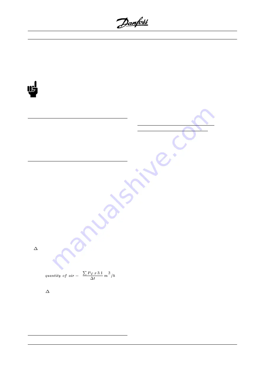
The quantity of air required for cooling AFD
can be calculated as follows:
1. Add up the values of P for all the AFDs to
be integrated in the same panel.
The highest cooling air temperature (t
IN
) present
must be lower than t
IN, MAX
40° C (104° F).
The day/night average must be 5°C (9° F) lower.
The outlet temperature of the cooling air must
not exceed: t
OUT, MAX
45° C (113° F).
2. Calculate the permissible difference between
the temperature of the cooling air (t
IN
) and
its outlet temperature (t
OUT
):
t= 45° C (113° F) -t
IN
.
3. Calculate the required
Insert
t in Kelvin
The outlet from the ventilation must be placed
above the highest-mounted AFD.
Allowance must be made for the pressure loss
across the filters and for the fact that the pressure
is going to drop as the filters are choked.
■
EMC-correct electrical installation
525-600 V units do not comply with European
EMC and Low Voltage Directives.
The following is a guideline to good engineering
practice, when installing drives. Following these
guidelines is advised, where compliance with EN
50081, EN 55011 or EN 61800-3
First environment
is required. If the installation is in EN 61800-3
Second environment,
then it is acceptable to
deviate from these guidelines. It is however not
recommended. See also
CE labelling, Emission
and
EMC test results
in this manual.
Good engineering practice to ensure
EMC-correct electrical installation:
•
Use only braided shielded/armored motor cables
and braided shielded/armored control cables. The
shield should provide a minimum coverage of 80%.
The shield material must be metal, not limited to
but typically copper, aluminum, steel or lead. There
are no special requirements for the line cable.
•
Installations using rigid metal conduits are not
required to use shielded cable, but the motor
cable must be installed in conduit separate from
the control and line cables. Full connection
of the conduit from the drive to the motor is
required. The EMC performance of flexible
conduits varies a lot and information from the
manufacturer must be obtained.
•
Connect the shield/armor/conduit to ground
at both ends for motor cables as well as for
control cables. See also
Grounding of braided
shielded/armored control cables
.
•
Avoid terminating the shield/armor with
twisted ends (pigtails). Such a termination
increases the high frequency impedance of the
shield, which reduces its effectiveness at high
frequencies. Use low impedance cable clamps
or EMC cable glands instead.
•
It is important to have good electrical contact
between the mounting plate on which the AFD is
installed and the metal chassis of the AFD unit.
Exception:
-
IP54/NEMA 12 units designed for wall mounting
-
VLT 8152-8600 (380-480 V) IP20/NEMA 1
-
VLT 8042-8062 (200-240 V) IP20/NEMA 1
MG.80.A7.22 - VLT is a registered Danfoss trademark
56
Rosewood STP ST42 General (Operation and Maintenance Manual - Part 4:
Section 6.3 Manufacturers Manuals 6.3.33 Danfoss VLT Aquadrive 8000) Vendor Manual
QP Id: VM207
Active: 03/09/2013
Page 62 of 208

