43
E
N
G
L
IS
H
the socket-head screw (
Fig. 29
) from the
bearing. Then tighten the screws right down
again (
Fig. 29
).
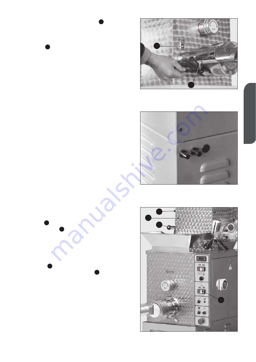
Plug the unit into the power supply socket
(
Fig. 29
) of the machine; let the safety
coupling click in.
5.2 CONNECTION TO THE WATER SYSTEM
For machines supplied with
an extrusion
sleeve cooling system,
connect the machi-
ne to the water system, install the sending
tube, (when it is non-existant: use a tap, pos-
sibly with screw-control) to the outer part of
the machine, in order to regulate the water
flow. The exit-flow tube must allow free water
discharge. We recommend that the water
pressure inside the machine, does not
exceed the 1.0 - 1.5 bar.
To connect the external parts, use a flexible
tube with an inside diameter of 13 mm,
safely fixed by a metal band with a screw
that can be closed with a screw-driver or key
(
Fig. 30
).
5.3 VARIANT FOR MOD. TRD 110 S
The TRD 110 S model uses the second tank
(
Fig. 31
) to enable dough to be kneaded
(press button
-
Fig. 31
) simultaneously
with the worm screw extrusion stage. This
allows output to be increased considerably.
Make the dough as shown for the main tank
then tip it into the main tank while rotating it
manually. To carry out this operation release
the knob
(
Fig. 31
) and rotate the tank by
means of the lever (
Fig. 31
), to obtain
continuous cycle production.
D
C
B
A
B
A
Fig. 30
Fig. 31
Fig. 29
A
B
A
C
D
B


