background image

ROSS

 CONTROLS

®

www.rosscontrols.com

C

ross

C

heCk

™ CC4 s

eries


s

afe

 C

ylinder

 C

ontrol


and

 s

top

 d

ouble

 V

alVes

i

ntegration

 g

uide

Summary of Contents for CrossCheck CC4 Series

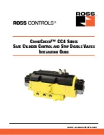
Page 1: ...ROSS CONTROLS www rosscontrols com CrossCheck CC4 Series Safe Cylinder Control and Stop Double Valves Integration Guide...

Page 2: ...ation Monitoring Requirements for 4 3 CC4 Series Valves Valve Operation 6 Feedback Monitoring General 7 Actuation Fault Monitoring 8 9 De Actuation Fault Monitoring Loss of Supply Pressure While Actua...

Page 3: ...and a pulse width of 0 4 ms to 0 8 ms Pulse testing the outputs to the solenoids on the CC4 valve at this frequency and duration does not affect the performance of the valve but does provide a method...

Page 4: ...th external pilot supply through the X port in the valve sub base When this conversion to external pilot supply is made the valve solenoid pilots will get their supply air from a source that is indepe...

Page 5: ...lbs 5 5 Nm Port size 1 2 3 4 216 in lbs 24 4 Nm F Reinstall the cover 2 screws Torque to 25 in lb 2 8 Nm See photo below left G Remove the pipe plug from the X port in the sub base H Install a new pil...

Page 6: ...as a PNP type sensor When the valves are in the center position the sensor outputs provide a voltage output signal to the inputs of the safety monitoring system When the valves are actuated the senso...

Page 7: ...ensor A Sensor B Safety Stop Signal Extend De actuation Fault Extend Solenoids Energized Extend Solenoids Energized Sensor A Sensor B Extend Solenoids De energized Retract Actuation Fault EN DN TON Ti...

Page 8: ...B Extend De Actuation Fault Extend De Actuation Timer Extend De Actuation Fault Reset Sensor A Sensor B Retract De Actuation Fault Retract De Actuation Timer Retract De Actuation Fault Loss of Supply...

Page 9: ...et of the safety control system should only be possible after the valve sensors indicate that both valves in the CC4 are in the center de actuated position both sensors switched on Safety System Reset...

Page 10: ...Reset the safety control system No NOTE 1 This validation test procedure should only be performed with a CC4 valve that is known to be functioning properly If basic valve function is in question plea...

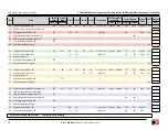
Page 11: ...losed ON ON Stop Yes 27 Reconnect solenoid signal wire to solenoid 12A 28 De energize solenoids 12A 12B OFF 29 Reset the safety control system No 30 Energize solenoids 12A 12B ON OFF ON ON OFF OFF 1 t...

Page 12: ...50 Disconnect sensor output wire from sensor B OFF OFF OFF OFF OFF OFF All closed None Pressure ON OFF Stop Yes 51 Attempt to energize solenoids 12A 12B ON 52 De energize solenoids 12A 12B OFF 53 Rec...

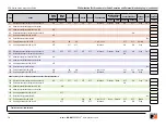
Page 13: ...e supply air from port 1 OFF OFF All closed ON ON Stop Yes 76 Resupply air to port 1 77 De energize solenoids 14A 14B OFF 78 Reset the safety control system No 79 Disconnect sensor output wire from se...

Page 14: ...t the safety control system 99 De energize solenoids 12A 12B OFF 102 Reset the safety control system No 103 Energize solenoids 12A 12B ON ON ON 1 to 2 4 to 3 OFF OFF Retract 104 De energize solenoids...

Page 15: ...a valve s exhaust port as this can adversely affect its operation Exhaust silencers must be resistant to clogging and must have flow capacities at least as great as the exhaust capacities of the valve...

Page 16: ...42 778 7251 www rossasia co jp ROSS UK Ltd UK Tel 44 1543 671495 www rossuk co uk ROSS SOUTH AMERICA Ltda Brazil Tel 55 11 4335 2200 www rosscontrols com br ROSS CONTROLS INDIA Pvt Ltd India Tel 91 44...

Reviews: