Cabling a Crosspoint Module • 7
Cabling a Crosspoint Module
If you are installing the Crosspoint module into a slot on the right-hand side of the
control panel, the Module Power Cable must be twisted to properly connect to the
Power Connector on the Crosspoint module. In this case, you may want to replace
the Module Power Cable with the longer cable provided (4800CR-361).
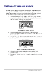
1.
Connect and secure the existing Module Control Link Cable to the PREV
port on the first module (1). This CAT5e cable with an RJ-45 connector on
either end is already installed in the control panel.
1
2
Front of Control Panel
Module Control
Link Cable
Figure 4: Module Control Link Cable
2.
Connect and secure the free end of the Module Control Link Cable
connected to the PREV port of the second module (2), to the NEXT port on
the first module (1).
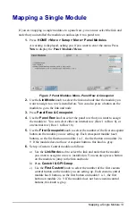
3.
Connect the black and white end of the Module Power Cable Adapter to the
Module Power Cable.
Front of Control Panel
Module Power
Cable
Module Power
Cable Adapter
Figure 5: Module Power Cable Adapter
4.
Connect the orange end of the Module Power Cable Adapter to the
Crosspoint module.
5.
Ensure that the Module Power Cable is properly connected to the remaining
modules.


