DETOUR User Guide (v3.0)
Installation • 13
ENET Connection
Optionally, there is an 10/100 Ethernet port for connecting to your facility network. This connection is used to
communicate with a DashBoard client for configuration and monitoring purposes.
Connect DETOUR to the same network as your DashBoard client computer or to a network that has a route to
the network your DashBoard client computer is on.
USB Connection
The micro USB connection is used for alarm detection and as a limited power input source.
Alarm Connection
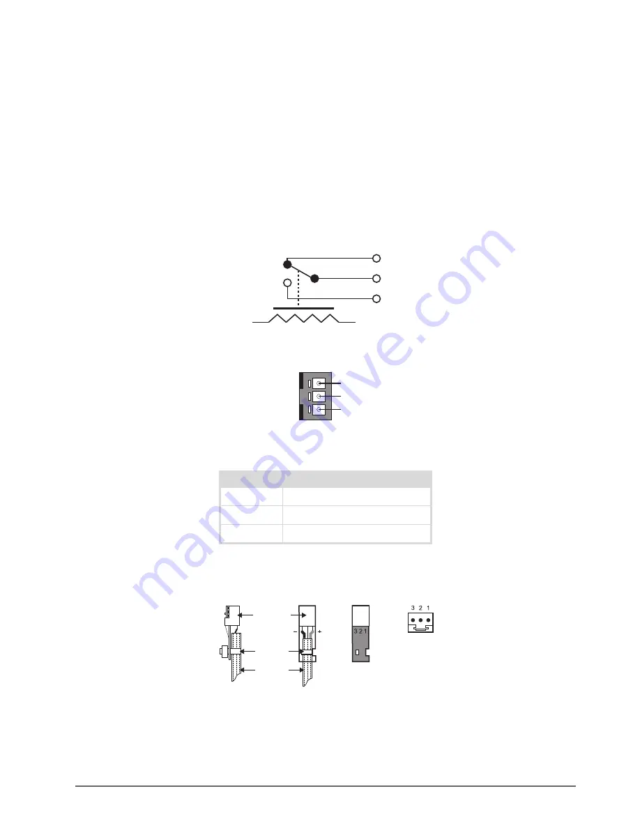
The ALARM port is a general purpose output that provides contact closure alarm state monitoring. Under normal
operation, the Center pin (2) is connected to Pin1 (normally closed). An alarm condition connects pin 2 to pin 3.
Figure 3.3 De-energized or Alarm State Equivalent Circuit
for the pinout assignment of the ALARM port on the chassis.
Figure 3.4 ALARM Port on DETOUR — Pinout Assignment
to for the signal pinouts for the 3-pin connector plug.
Figure 3.5 Connector Plug — Pinouts for Alarm Port
Table 3.1 Alarm Pinouts
Pin Number
Function
1
Normally closed
2
Common
3
Normally open
PIN 2
PIN 3
PIN 1
3
2
1
Connector
End View
Connector
Side View
Cable
Connector
Tie Wrap
Connector
Top Views
(without cable)
Summary of Contents for 9201DR-104-03
Page 1: ...DETOUR User Guide...
Page 6: ......
Page 26: ...26 DashBoard Menus DETOUR User Guide v3 0...
Page 28: ...28 Warranty and Repair DETOUR User Guide v3 0...
Page 32: ...32 Technical Specifications DETOUR User Guide v3 0...


