ACO-2200 User Guide (v5.0)
Hardware Overview • 11
Hardware Overview
This chapter outlines the basics of operating the ACO-2200.
Front Panel Overview
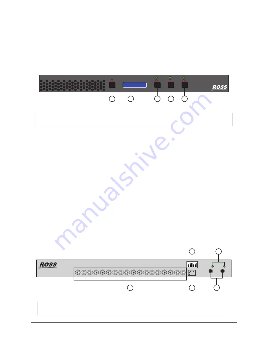
shows the ACO-2200 Front Panel. Descriptions of the Front Panel controls and indicators appear below.
Figure 3.1 ACO-2200 — Front Panel
The red LED illuminates to indicate a fault condition. Pressing the
FAULT
button cycles the display between
fault status messages and the ACO-2200 IP Address.
2. LED Display
The LED Display cycles through a series of Status messages including the IP Address of the unit, and fault status
messages.
3. Automatic/Manual Mode Button and LEDs
This button enables the user to select Automatic or Manual mode.
4. Primary/Backup Mode Button and LEDs
This button enables the user to select either the Primary or Backup inputs.
5. Panel Lock/Unlock Button and LEDs
This button allows the user to select if the front panel buttons are locked or unlocked.
Rear Panel Overview
shows the ACO-2200 Rear Panel. Descriptions of the rear-panel connectors appear on the following
pages.
Figure 3.2 ACO-2200 — Rear Panel
1) FAULT Button and LED
3) Automatic/Manual Mode Button and LEDs
5) Panel Lock/Unlock Button and LEDs
2) LED Display
4) Primary/Backup Mode Button and LEDs
1) BACKUP - # - PRIMARY BNCs
3) DIP Switches
5) PSU Presence LEDs
2) Ethernet 100-Base T Connection
4) PSU Connectors
ACO-2200
CHANGEOVER
1 2 3 4
ACO-2200
10.xx.xx.xx
2
FAULT
1
AUTO
MANUAL
PRIMARY
BACKUP
LOCK
UNLOCK
5
4
3
1
100-BaseT
BACKUP
— 2 —
BACKUP
— 1 — PRIMARY
PRIMARY BACKUP
BACKUP
BACKUP
BACKUP
— 3 —
— 4 —
— 5 —
— 6 —
PRIMARY
PRIMARY
PRIMARY
PRIMARY
ACO-2200
+12V
PSU 1
+12V
PSU 2
2
1
3
4
2
3
4
5


