18 • Functional Check Procedures
ACO-2200 User Guide (v5.0)
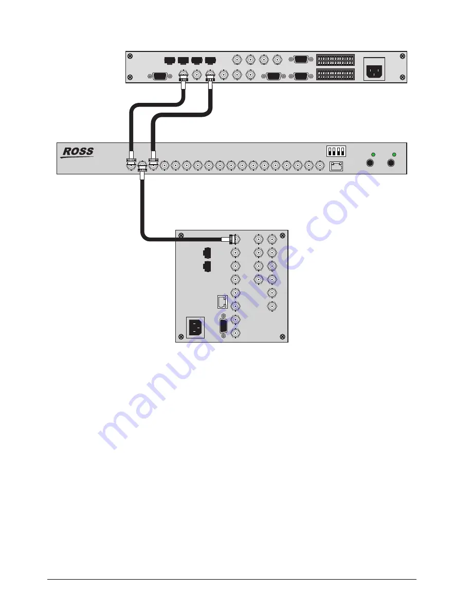
Figure 5.1 Functional Check Connections
The signal inputs are nominally different in order to easily verify which signal is switched to the output.
3. Apply power to the ACO-2200 by connecting it to the power source(s). The instrument runs its power-on
initialization process.
4. Check that no error messages appear on the LCD display.
5. Much of the functional check can be carried out immediately. However, some calibration settings are only
guaranteed once functional temperature has stabilized (which should occur after 20 minutes). It is good
practice to soak the instrument before proceeding.
6. User settings are made using DashBoard.
Recommendation
The ACO-2200 menu system contains an appreciable number of pre-programmed and user selectable settings. All
of these settings are programmed using the factory default procedure, and a select few are then adjusted during
testing and alignment. This is especially true of the Calibration menu, where settings relating to the fundamental
operation of each individual ACO-2200 are stored. If memory corruption occurs, some or all of the settings may
need to be re-instated.
For More Information on...
• the entire menu system refer to the chapter “
100-BaseT
BACKUP
— 2 —
BACKUP
— 1 — PRIMARY
PRIMARY BACKUP
BACKUP
BACKUP
BACKUP
— 3 —
— 4 —
— 5 —
— 6 —
PRIMARY
PRIMARY
PRIMARY
PRIMARY
TV SIGNAL GENERATOR
WAVEFORM MONITOR
Composite Video
Analog Color Black
ACO-2200
ACO-2200
+12V
PSU 1
+12V
PSU 2
1
3
4
2


