2
ROSS
CONTROLS
®
Construction: Dual poppet.
Mounting Type: Line mounted.
Pilot Solenoid: According to VDE 0580. Enclosure rating according to DIN
400 50 IP 65. Connector socket according to DIN 43650 Form A. Three
solenoids, rated for continuous duty.
Standard Voltages/Pilot Solenoids Power Consumption
(each solenoid): 24 volts DC; 110 volts AC, 50 Hz; 120 volts AC, 50/60 Hz.
5.8 watts nominal on AC and DC; 6.5 watts maximum on AC and DC.
Enclosure Rating: IP65, IEC 60529.
Electrical Connection: EN 175301-803 Form A, or M12.
Ambient Temperature: 15° to 122°F (-10° to 50°C).
Media Temperature: 40° to 175°F (4° to 80°C).
Flow Media: Filtered, lubricated or unlubricated air (mineral oils according
to DIN 51519, viscosity classes 32-46).
Inlet Pressure: 30 to 120 psig (2 to 8.3 bar).
Pressure Switch (Status Indicator) Rating:
Contacts - 5 amps at 250 volts AC, or 5 amps at 30 volts DC.
Monitoring: Dynamically, cyclically, internally during each actuating and
de-actuating movement. Monitoring function has memory and requires an
overt act to reset unit after lockout.
Mounting orientation: Preferably horizontally (valve on top of base) or
vertically with pilot solenoids on top.
Functional Safety Data: Category 4 PL e; B10D: 20,000,000;
PFHD: 7.71x10
-9
; MTTFD: 301.9 (n
op
: 662400).
Certifications: CE Marked for applicable directives, BG, CSA/UL, TSSA
for appropriately tested valves.
Vibration/Impact Resistance: Tested to BS EN 60068-2-27.
STANDARD SPECIFICATIONS
IMPORTANT NOTE: Please read carefully and thoroughly all the CAUTIONS and WARNINGS on page 4.
The overall function of the DM
2®
Series E valve is that of a 3-way, 2-position
(3/2) normally closed solenoid valve. When in the normal at-rest condition,
the valve inlet port (1) is closed and the outlet port (2) is open to the exhaust
port (3). Normal actuation of the valve opens the valve inlet port (1) to the
outlet port (2) and closes the exhaust port (3). De-actuation returns the
valve to the normal at-rest condition. However, being a double valve, there
are two solenoid pilots and two sets of valve elements for redundancy. That
being the case, both solenoids must be energized simultaneously in order
for the valve to actuate normally to supply air from inlet to outlet. Likewise,
both solenoids should be de-energized simultaneously in order to de-actuate
and return the valve to its normal at rest condition, thus shutting off the inlet
and dumping downstream air to exhaust.
If one of the valve elements does not shift fully and in sync with the other
within a preset discordance time, the valve will go into a lockout condition
such that any downstream pressure in the outlet port (2) will be exhausted
to atmosphere through exhaust port (3). There should also be a small, but
audible, flow of air out the exhaust port (3) as long as the valve remains in
the lockout condition.
If your valve is supplied with the optional status indicator, a lockout condition
should be indicated by a change in state of the status indicator pressure
switch. See Lockout Indication on page 1.
In order to reset the valve and return it to the "ready-to-run" condition, with
supply pressure applied and the pilot solenoids de-energized, momentarily
energize the reset solenoid (at least 200 milliseconds). After resetting the
valve the lockout condition should be cleared, there should be no pressure
present at outlet port (2) and there should no longer be any audible flow of
air to exhaust port (3).
If momentarily energizing the reset solenoid does not clear the lockout
condition, the valve may need to be serviced. See Valve Maintenance below.
VALVE OPERATION
VALVE RESET INFORMATION
When and why does the valve require a reset signal?
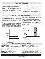
The valve will only require a reset when the valve has detected asynchronous
movement of the two independent internal elements. This condition will be
indicated by a fault signal from the pressure switch feedback device and
an audible leak from the silencer. Reset is accomplished by applying a
momentary signal to the reset solenoid. The DM2
®
Series E valves have
an anti-tie-down feature that requires both main valve solenoids to be de-
energized while resetting.
Why will my valve not reset?
1. There are a few common conditions that can prevent reset from occurring.
2. If the main valve solenoids are energized the valve will not reset. This is
a safety feature of the DM2
®
Series E valves that prevents unintended
pressure output from occurring upon valve reset. There should be at least
a 200 ms delay between removing power from the reset solenoid and
applying power to the main valve solenoids.
3. If the pneumatic supply to port 1 is not sufficient the valve will not reset.
This is not unusual for initial testing and startup if full plant pressure and
volume is not applied and quick connects or small hoses are used.
4. If the supply pressure was removed before de-energizing the valve it
is possible that both valve elements are in the faulted condition. This
condition results in a greater leakage rate to the exhaust port when the
supply is reapplied, and increases the insufficient supply issue mentioned
in item #2.
5. The reset solenoid may be mounted backwards. In this case energizing the
reset solenoid will result in the release of air through the reset solenoid’s
exhaust port (through the nut mounted on the stem of the solenoid) and
no reset action can occur.
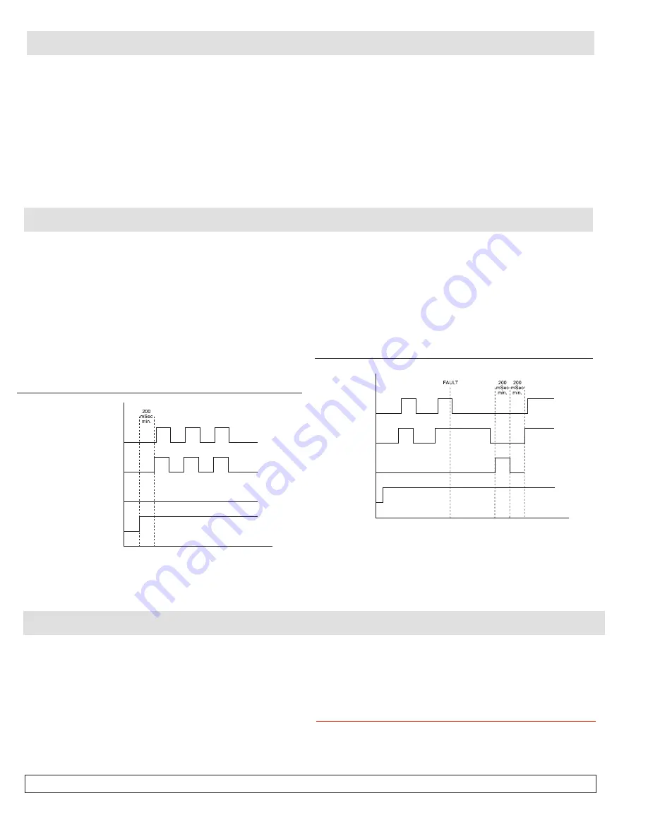
DM2
®
Operation Timing Chart
Outlet
Pressurized
Reset
Signal
Main
Solenoids
Supply
Pressure
Applied
1. Operating signal to main solenoids should be dual
channel, concurrent operation. Discordance of signals
should be less than 25 msec.
2. Turning off supply pressure while valve is energized
will result in a fault and then valve must be reset.
3. Fault detection is constant.
DM2
®
Reset Timing Chart
Outlet
Pressurized
Reset
Signal
Main
Solenoids
Supply
Pressure
Applied
1. Reset anti-tie-down feature requires main solenoids to be off
during reset.
2. Reset duration is momentary - 200 msec. min. recommended.
3. At end of reset signal, time is required for pilot chambers to
refill before operation - 200 msec. recommended.
4. Fault detection is constant.
5. Turning off supply pressure while valve is energized will result
in a fault and then valve must be reset.

