3-4
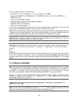
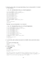
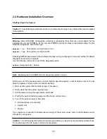
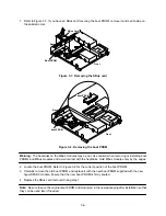
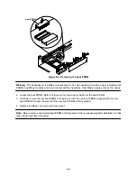
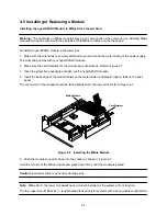
5. Carefully remove the module (lift vertically) until the MBus connector is out of the slot.
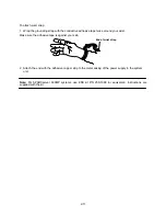
6. Place the module on the antistatic mat supplied with the hyperSPARC module kit.
7
.
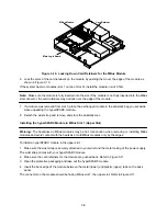
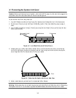
Follow steps 4–6 to remove the module from the second slot if two modules were installed.
Note: Be sure to save the original boot PROM and module(s) in the new packaging after installation so that
they can be used later if needed.
3.3 Setting the MBus Clock Speed Jumpers
You must set the system clock speed jumpers to 40 MHz MBus on the main logic board to assure correct
operation of the hyperSPARC MBus module. The following sections describe the jumper settings for the two
different types of main logic boards.
Board with Three Jumpers
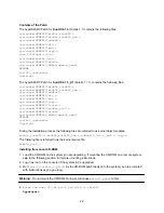
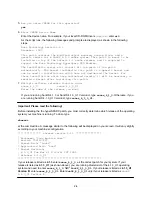
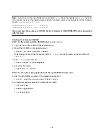
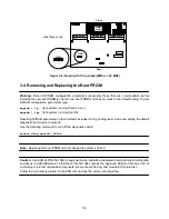
One type of board has three jumpers: J1401, J1403, and J1404. All three jumpers must be set as indicated
in Figure 3-5 to assure correct operation of the hyperSPARC module.
Board with One Jumper
The other type of board has one jumper: J1401. This jumper must be set as indicated in Figure 3-6 to assure
correct operation of the hyperSPARC module.
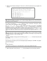
Note: If the clock speed jumpers are not set correctly, the system may fail to boot.
Use needle-nose pliers to set the clock speed jumpers after referring to Figure 3-6 to determine the correct
jumper settings.
Front
Rear
J1401
J1404
J1403
J1401 Pins = No Jumper
J1403 Pins = 1 to 2
J1404 Pins = 1 to 2
SIMM
slots
MBus slot 1
MBus slot 0
SBus slot 1
SBus slot 0
SBus slot 3
SBus slot 2
J1404
J1403
J1401
Figure 3-5. Board with Three Jumpers (MBus = 40 MHz)
Summary of Contents for hyperSPARC
Page 2: ...hyperSPARC Module Installation Guide TM...
Page 9: ...1 4...
Page 21: ...2 12...
Page 55: ...5 10...

