background image

4-11

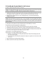
4.7 Starting Up the System and Verifying Installation

Warning: Before powering on your system again, be sure to install the cover. It is not safe to operate the
SPARCstation 20 without the top cover in place.

Warning: This device is equipped with a 3-wire grounded power cord. To reduce the risk of electrical shock,
always plug the power cord into a properly grounded power outlet.

Caution: Always allow 10 seconds between turning off the power and turning the power back on. This pause
prevents possible damage to power supply components in your system unit.

Turn the power switches on in this order:

a. Monitor

b. External drives

c. System Unit

To power-up the system and verify installation set the power switch on the chassis to the ON position.

Important: The power-on self test (POST) will run on each CPU. Therefore, the length of time for POST to
complete will depend on the number of CPUs installed in your system. Do not be alarmed if initially you do
not see any display on the monitor. In a configuration with four processors, POST completes in approximately
eight minutes.

Note: Once 

power-on self tests

 are completed and functional modules are recognized, the operating

system will configure itself automatically to take advantage of all available processors.

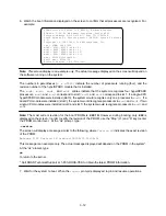
4. Watch the boot information displayed on the screen to confirm that all processors are recognized. For

example:

SPARCstation 20 Series (4 X RT625), Keyboard Present
ROM Rev. 2.22, 64 MB memory installed, Serial #232.
Ethernet address 8:0:20:b:5f:7, Host ID: 710000e8.
SunOS Release 5.3 Version generic [UNIX(R) System V Release 4.0]
Copyright (c) 1983–1993, Sun Microsystems, Inc.
cpu = SUNW, Sun 4/600
mod0 = ROSS, RT625 (mid = 8)
mod1 = ROSS, RT625 (mid = 9)
mod2 = ROSS, RT625 (mid = 10)
mod3 = ROSS, RT625 (mid = 11)
mem = 65204K (0x3fad000)
avail mem = 63348736
Ethernet address = 8:0:20:b:5f:7

Note:

This screen display is an example only. The actual message displayed on the screen will depend on

the software running on the system.

The numbers in parentheses (

4 x RT625)

 indicate the number of processors running (four), and the

revision number of the hyperSPARC module that is installed.

Summary of Contents for hyperSPARC

Page 1: ...service in house repair center WE BUY USED EQUIPMENT Sell your excess underutilized and idle used equipment We also offer credit for buy backs and trade ins www artisantg com WeBuyEquipment REMOTE IN...

Page 2: ...hyperSPARC Module Installation Guide TM...

Page 3: ...d Computer Software clause at DFARS252 227 7013andFAR 52 227 19 The product described in this manual may be protected by one or more U S patents foreign patents or pending applica tions TRADEMARKS ROS...

Page 4: ...Part 1 On the system with the CD ROM drive upgrade server 2 6 Part 2 On the system being upgraded with the hyperSPARC module client 2 6 2 4 Hardware Installation Overview 2 9 Shutting Down the System...

Page 5: ...6 Installing the System Board in the Enclosure 5 8 5 7 Starting Up the System and Verifying Installation 5 9 Appendix A Troubleshooting Guide Potential Upgrade Problems A 1 A 1 Correct Patches for So...

Page 6: ...Installation Important The hyperSPARC module is designed to run in a Sun SPARCstation 10 SPARCstation 20 or SPARCserver 600MP environment which includes a minimum of 140W power supply Operation of hy...

Page 7: ...n off the system power you must halt the operating system or loss of data can occur To shut down the system and give users a shutdown warning 1 Back up the system files and data to tape if necessary 2...

Page 8: ...risk of ESD damage Handle board by edges only Store board in antistatic bag provided 1 3 Using the Disposable Wrist Strap The wrist strap is a device that provides grounding for static electricity be...

Page 9: ...1 4...

Page 10: ...and module s in the new packaging after installation so that they can be used later if needed Typographic Conventions This chapter uses the following fonts to describe system messages and user input t...

Page 11: ...as Solaris 1 1 or Solaris 1 1 1 respectively You can do this by typing uname r or showrev at the command line which will print out the version of SunOS that you are running If you are running Solaris...

Page 12: ...n4m GENERIC locore o sys sun4m GENERIC module_conf o sys sun4m GENERIC vmunix sys sun4m GENERIC_SMALL vmunix_small README install_hypersparc Copyright During the installation process the following fil...

Page 13: ...s_4_1_3 sunos_4_1_3_U1 Enter the name of the release you want If you are running SunOS 4 1 3 or SunOS 4 1 3_U1 Version A type sunos_4_1_3 Otherwise if you are running SunOS 4 1 3_U1 Version B type sun...

Page 14: ...SS CD ROM Note Answer no to step 9 if you have already installed a hyperSPARC patch 10 Install client kernel in usr stand yes no yes This will install vmunix and vmunix_small in usr stand These extra...

Page 15: ...ROM Part 1 On the system with the CD ROM drive upgrade server 1 Log in as root on the console of the upgrade server 2 Mount the CD ROM on the upgrade server mount rt hsfs dev sr0 cdrom Note Arrange to...

Page 16: ...un4m GENERIC module_ross625_asm o x sys sun4m GENERIC addsub o x sys sun4m GENERIC div o x sys sun4m GENERIC mul o x sys sun4m GENERIC copy o x sys sun4m GENERIC locore o x sys sun4m GENERIC module_co...

Page 17: ...nel that supports hyperSPARC 14 Install generic kernel yes no yes Type yes to confirm If you do not install the generic kernel you will have to create a customized kernel to run hyperSPARC Saving old...

Page 18: ...the diagnostic switch setenv diag switch false Note Replacing the boot PROM will not change the system s host id Before you turn off the system power you must halt the operating system or loss of dat...

Page 19: ...lking across a carpet and touching a board or by other similar causes Before handling any board make sure you dissipate your body s charge Touch a conductive surface of the chassis or other element co...

Page 20: ...your wrist Make sure the adhesive tape is against your skin End of wrist strap 2 Attach the end with the adhesive copper strip to the metal casing of the power supply in the system unit Note For SPAR...

Page 21: ...2 12...

Page 22: ...in the same machine Important The hyperSPARC module is designed to run in a Sun SPARCstation 10 SPARCstation 20 or SPARCserver 600MP environment which includes a minimum of 140W power supply Operation...

Page 23: ...w Figure 3 1 Location of Captive Screw on the Rear Panel 2 Use the Phillips screwdriver to press the retainer clip while you loosen the cover from the back panel with your other hand Retainer clip Fig...

Page 24: ...tion provides the ground path necessary to safely remove and install the printed circuit boards and components In addition keep the internal power supply cable connected to the main logic board Cautio...

Page 25: ...two different types of main logic boards Board with Three Jumpers One type of board has three jumpers J1401 J1403 and J1404 All three jumpers must be set as indicated in Figure 3 5 to assure correct o...

Page 26: ...lpr for systems running SunOS Resetting NVRAM parameters to their defaults includes turning on diagnostic mode and setting the default diagnostic boot device to network Use the following command to tu...

Page 27: ...alling boot PROMs and MBus modules and avoid contact with the heatsinks Hold MBus modules only by the edges 2 Locate the boot PROM Refer to Figure 3 8 for the correct position of the boot PROM 3 Caref...

Page 28: ...the protective packaging and take out the hyperSPARC module 4 Insert the back edge of the module between the metal lower and plastic upper tabs on the back panel The connector on the module should be...

Page 29: ...ach the wrist strap and remove and store the antistatic mat Installing the hyperSPARC Module in MBus Slot 1 Upper Slot Warning The heatsinks on MBus modules may be hot Use caution when removing or ins...

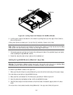
Page 30: ...function The top upper slot MBus slot 1 is optional and is used only for systems with a dual module configuration MBusModule Main Logic Board Card Retainer Figure 3 12 Locking Down Card Retainers for...

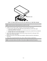
Page 31: ...ly at an angle as shown in Figure 3 13 and gently glide the hinge tabs on the cover into the tab slots on the front of the system unit Continue to hold onto the cover Back Front Figure 3 13 Installing...

Page 32: ...the power and turning the power back on This pause prevents possible damage to power supply components in your system unit Turn the power switches on in this order a Monitor b External drives c System...

Page 33: ...d0 and mod1 correspond to slot 0 mod2 and mod3 correspond to slot 1 If a single CPU hyperSPARC module were installed slot 0 the system would recognize only one processor in mod0 If a dual CPU module w...

Page 34: ...r in the same machine Important The hyperSPARC module is designed to run in a Sun SPARCstation 10 SPARCstation 20 or SPARCserver 600MP environment which includes a minimum of 140W power supply Operati...

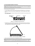
Page 35: ...emove the lock block and put it aside Lock block screw Corner screw Power supply screw do not loosen Figure 4 1 Lock Block Screw and Corner Screw 4 Grasping the cover at the back of the machine lift i...

Page 36: ...ion provides the ground path necessary to safely remove and install the printed circuit boards and components In addition keep the internal power supply cable connected to the MLB Caution Make sure th...

Page 37: ...iginal boot PROM and module s in the new packaging after installation so that they can be used later if needed 4 3 Setting the MBus Clock Speed Jumper There are clock speed J1401 and serial port J0801...

Page 38: ...e the following command to turn off the diagnostic switch setenv diag switch false Note Replacing the boot PROM will not change the system s host id Caution Use ESD kit P N 250 1088 or equivalent when...

Page 39: ...edges 2 Locate the boot PROM Refer to Figure 4 6 for the correct position of the boot PROM 3 Carefully remove the old boot PROM and replace it with the new boot PROM supplied with the new hyperSPARC m...

Page 40: ...er to Figure 4 7 3 Open the protective packaging and take out the hyperSPARC module 4 Insert the back edge of the module between the metal lower and plastic upper tabs on the back panel The connector...

Page 41: ...rist strap and remove and store the antistatic mat Installing the hyperSPARC Module in MBus Slot 1 Upper Slot Warning The heatsinks on MBus modules may be hot Use caution when removing or installing M...

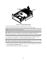
Page 42: ...only for systems with a dual module configuration 6 Lock the arms of the card retainers on the module by pushing them over the edge of the module If the system has two modules slot 1 on top of slot 0...

Page 43: ...are locked into the chassis slots Lower the cover onto the chassis See Figure 4 10 Front Figure 4 10 Installing the System Unit Cover 2 Replace the lock block and use a Phillips screwdriver to tighten...

Page 44: ...u do not see any display on the monitor In a configuration with four processors POST completes in approximately eight minutes Note Once power on self tests are completed and functional modules are rec...

Page 45: ...ision for the boot PROMs is 2 22 1H However during booting only 2 22 is displayed on the screen In order to verify the revision of the PROM use the Stop L1 and A key to enter the PROM monitor level At...

Page 46: ...2 when working on 600MP system boards Use ESD kit P N 250 1088 or equivalent Instructions are included in the kit Caution The system chassis power must be turned off and the AC power cord must remain...

Page 47: ...with the kit To access the system board 1 Move the system so that you have easy access to the enclosure 2 Place the ESD mat in the area where you are working The ESD mat and the wrist grounding strap...

Page 48: ...sary b Label all cables that are connected to serial ports A and B and any cables that are connected to any SBus cards Then remove all of the cables 5 Use a 2 5 mm Allen wrench to remove the screws se...

Page 49: ...tch setenv diag switch false Note Replacing the boot PROM will not change the system s host id Caution Use ESD kit P N 250 1088 or equivalent when installing integrated circuits printed circuit boards...

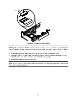
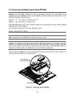
Page 50: ...d unpredictable results Note Be sure to save the original boot PROMs and module s in the new packaging after installation so that they can be used later if needed 5 4 Removing the Module Caution Use E...

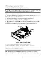
Page 51: ...two hyperSPARC modules on the 600MP system board module 0 and module 1 A module must be installed in the slot 0 position A module in the second slot 1 is optional the second slot is used only for dual...

Page 52: ...ctor press down on the corner of the module Repeat this step on the remaining corners 7 Replace and fasten the slotted fillister screws on the four standoffs Note Do not substitute pan head screws for...

Page 53: ...bent pins or other damage Correct the problems before attempting to reinsert the board 3 Press firmly on the board rear panel to seat the board onto the backplane connectors The extraction levers sho...

Page 54: ...processors running four and the revision number of the hyperSPARC module that is installed The mod0 mod1 mod2 and mod3 entries indicate that the system recognizes four hyperSPARC processors mod0 and m...

Page 55: ...5 10...

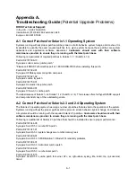
Page 56: ...opsis XView 3 0 Jumbo patch The latest release of Solaris 1 x is Solaris 1 1 2 SunOS 4 1 4 This release offers full hyperSPARC support and comprehends many of the outstanding errata A 2 Correct Patche...

Page 57: ...s with software maintenance contracts 3 Anonymous ftp on the Internet from the host sunsite unc edu in the directory pub sun info sun patches as PatchReport or Recommended Notes 101508 conflicts with...

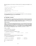
Page 58: ...blem Solutions SunOS 4 1 4 incorporates the available patches of SunOS 4 1 3_U1 and some bug fixes If your are installing SunOS 4 1 4 there are ways to accomplish this with hyperSPARC First you can us...

Page 59: ...f this occurs please contact ROSS Technical Support If your system is either SPARCstation 10 or SPARCstation 20 the minimum boot PROM revision supporting ibuf off is 2 19 3 If your system is a SPARCse...

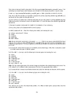
Page 60: ...ms SPARCserver 600MP SPARCstation 10 Description ROSS has uncovered several performance related errata in Solaris 2 3 Customers may see lower than expected performance with Solaris 2 3 while running c...

Page 61: ...with either 1 or 2 DataRam Expansion Memory boards installed With this configuration the system will not boot the operating system Corrective Action Customers should remove the Dataram expansion memor...

Page 62: ...eceive depends on the CPU s that your system is running Note Boot PROM revisions 2 22 1H SPARCstation 10 20 2 14 3H SPARCserver 600 and later will also display information regarding the external cache...

Page 63: ...B 5 Identifying the Speed of a hyperSPARC Module The first two digits on the label located below the serial number on the MBus connector indicate the speed of the hyperSPARC module 150 indicates a 150...

Page 64: ...ized ROSS service facility worldwide No product will be accepted by ROSS without the appropriate Return Merchandise Authorization documentation e This Limited Warranty Statement gives the customer spe...

Page 65: ...ow these steps in order to make your return process smooth Contact ROSS at 512 892 7802 extension 556 to request a return form This form will be faxed to you by the end of the next working day Fill ou...

Page 66: ...service in house repair center WE BUY USED EQUIPMENT Sell your excess underutilized and idle used equipment We also offer credit for buy backs and trade ins www artisantg com WeBuyEquipment REMOTE IN...

Reviews: