5-2
5.2 Removing the System Board from the Enclosure
Caution: Refer to the “Shutting Down the System” section on page 1-2 to make sure the system is shut off.
Turn off the power at the main AC breaker before you insert or remove boards and disk drives. Do not
disconnect the AC power cord from its receptacle. The system chassis power must be turned off, and the
power cord must remain plugged in to ensure a proper ground.
Caution: Use ESD kit P/N 250-1088 (or equivalent) when installing integrated circuits, printed circuit boards,
and drives in a SPARCserver 600MP. ESD kit P/N 250-1088 contains the Sun approved ESD mat that has
0.25” of cushioning to protect underside components, prevent board flexing, and provide ESD protection.
Instructions for use are included with the kit.
To access the system board:
1. Move the system so that you have easy access to the enclosure.
2. Place the ESD mat in the area where you are working.
The ESD mat and the wrist grounding strap will protect against electrostatic discharge. Connect the ground
clip to the chassis and mat.
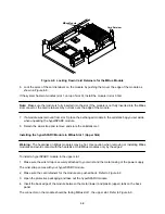
3. If the system is a 56-inch data cabinet, use a #2 Phillips screwdriver to remove the vented, rear panel.
Refer to Figure 5-1. Then, go to step 4.
If the system is a 12-slot office pedestal, go to step 4.
There is no panel or cover to remove to access the board in a 12-slot system.
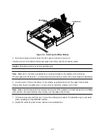
If the system is a 5-slot office pedestal, remove the top cover:
a. Locate the top cover release knob. Turn the knob counterclockwise one quarter turn until you hear
a click. Refer to Figure 5-2.
b. Slide the top cover back and lift the cover off of the chassis. Set the cover aside. Go to step 4.
Rear panel
Kick panel
Figure 5-1.
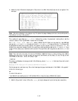
Removing the Panel to Access the Board in a 56-inch Data Cabinet
Summary of Contents for hyperSPARC
Page 2: ...hyperSPARC Module Installation Guide TM...
Page 9: ...1 4...
Page 21: ...2 12...
Page 55: ...5 10...

