5-3
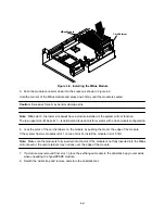
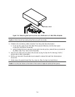
Release knob
Figure 5-2. Removing the Top Cover to Access the Board in a 5-Slot Office Pedestal
Caution: Attach the wrist grounding strap that came with the module.
4. Unfasten and set aside any cable connectors from the system board back panel.
a. To remove the system board, first detach the keyboard, Ethernet, and other back panel
connectors. Label these if necessary.
b. Label all cables that are connected to serial ports A and B, and any cables that are connected to
any SBus cards. Then, remove all of the cables.
5. Use a 2.5 mm Allen wrench to remove the screws securing the board to the card cage. Set the
screws aside for later reinstallation.
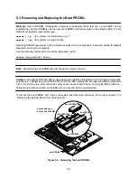
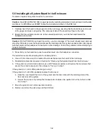
6. Pull the curved ends of the extraction levers outward to release the board from the backplane
connectors.
7. Gently remove the system board from the enclosure. Place the board on the ESD mat.
Caution: Avoid contact between the bottom of the board with adjacent cards and filler panels.
Summary of Contents for hyperSPARC
Page 2: ...hyperSPARC Module Installation Guide TM...
Page 9: ...1 4...
Page 21: ...2 12...
Page 55: ...5 10...


