5-6
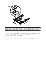
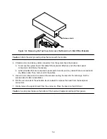
2. Hold the module by the edges near the connector.
3. Lift the module off the connector.
Note: Do not “rock” the module while removing it; connector damage could result.
4. Place the module on the ESD mat or in an antistatic bag.
5. To install a hyperSPARC module, follow the steps in “Installing or Replacing a Module.”
Note: Be sure to save the original boot PROMs and module(s) in a safe place after installation so that they
can be used as spares if needed.
5.5 Installing or Replacing a Module
To install or replace a hyperSPARC module, first remove the system board from the card cage, then refer
to Section 5.2 “Removing the System Board from the Enclosure.” The system board can have up to two
hyperSPARC modules on the 600MP system board: module 0 and module 1.
A module must be installed in the
slot 0 position. A module in the second slot (1) is optional; the second slot
is used only for dual-module configurations.
Caution: Use the wrist grounding strap that came with the module.
Note: Visually inspect the pins on the hyperSPARC module and in the MBus connector to make sure the pins
are not bent before installing the module.
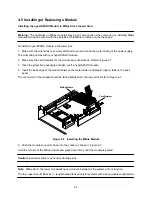
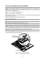
Figure 5-5. Installing the hyperSPARC Module – 600MP System Board
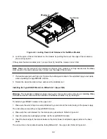
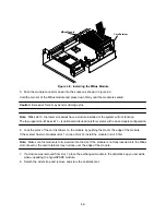
1. Remove the slotted fillister head screws from each standoff of the module.
When installing a module in slot 1 on the 600MP system board, you must first move the two standoffs used
for SBus slot 3 to the slot 1 location.
2. Open the protective packaging and take out the hyperSPARC module.
3. Hold the card by the edges near the connector.
4. Place the module on the four screw-in standoffs.
Summary of Contents for hyperSPARC
Page 2: ...hyperSPARC Module Installation Guide TM...
Page 9: ...1 4...
Page 21: ...2 12...
Page 55: ...5 10...


