5-7
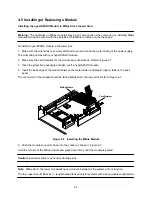
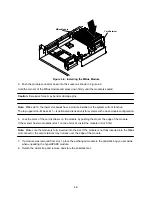
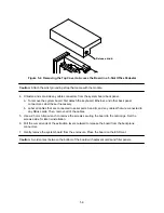
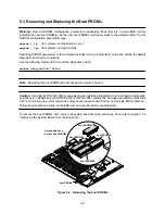
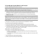
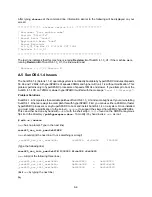
Make sure the module is seated on the four standoffs.
5. Align the module on the module connector, ensuring that the keyed notches on the connector match
the bumps on the receiving connector. Firmly but gently press down until the module is fully seated on
the connector.
Do not “rock” the module onto the connector; press down on the corner of the module.
6. Starting from a corner opposite from the connector, press down on the corner of the module.
Repeat this step on the remaining corners.
7. Replace and fasten the slotted fillister screws on the four standoffs.
Note: Do not substitute pan head screws for the fillister head screws originally removed from the standoffs.
Fillister head screws must be used because the head on a fillister head screw is taller. Refer to Figure 5-6.
Fillister Head
Slot
Pan Head
Figure 5-6. Fillister Head and Pan Head Screws
Caution: Because of the tight clearance, use caution when replacing the fillister head screws. Do not allow
the screwdriver to contact the hyperSPARC module.
Summary of Contents for hyperSPARC
Page 2: ...hyperSPARC Module Installation Guide TM...
Page 9: ...1 4...
Page 21: ...2 12...
Page 55: ...5 10...


