F3.16
© 2016,
ROSS
CONTROLS
®
.
All Rights Reserved.
IMPORTANT NOTE:
Please read carefully and thoroughly all of the
CAUTIONS, WARNINGS
on the inside back cover.
Online Version
Rev. 11/14/16
2
3
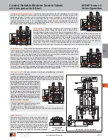
Mounting brackets are required to install valve in the system, see M DM
2®
Series C accessories for ordering information page F3.18.
Construction:
Dual Poppet.
Mounting Type:
Base mounted.
Pilot Solenoids:
According to VDE 0580. Enclosure rating according to
DIN 400 50 IP 65. Three solenoids, rated for continuous duty.
Standard Voltages:
24 volts DC.
Pilot Solenoids Power Consumption
(each solenoid)
:
Primary and reset solenoids:
1.2 watts on DC.
Enclosure Rating:
IP65, IEC 60529.
Solenoid & Status Indicator Connection:
M12, 5-pin Male Receptacle, A-Coded.
Ambient Temperature:
15° to 122°F (-10° to 50°C).
Media Temperature:
40° to 175°F
(4° to 80°C).
Flow Media:
Filtered, lubricated or unlubricated (mineral oils according to
DIN 51519, viscosity classes 32-46); 5-micron recommended.
Inlet Pressure:
30 to 150 psig (2 to 10 bar). Under certain circumstances,
such as maximum restriction of the adjustable flow control or a very large
downstream system volume, the minimum inlet pressure may need to be
set up to 60 psig (4 bar) to prevent nuisance valve faults.
Pressure Switch (Status Indicator) Rating:
5 amps at 30 volts DC.
Monitoring:
Dynamically, cyclically, internally during each actuating and
de-actuating movement. Monitoring function has memory and requires
an overt act to reset unit after lockout.
Mounting Orientation:
Vertically with pilot solenoids on top.
Functional Safety Data:
Category 4 PL e; B10d: 20,000,000; PFHd:
7.71x10
-9
; MTTFd: 301.9 (n
op
: 662400).
Certifications
: CE Marked for applicable directives, CSA/UL.
Vibration/Impact Resistance:
Tested to BS EN 60068-2-27.
Port Size
Basic Size
Transducer
Valve Model Number
*
C
V
Weight
lb (Kg)
Inlet
Outlet
1 to 2
2 to 3
3/4
3/4
8
With
MDM2C
N
A55A23
3.7
8.5
16.3 (7.4)
3/4
3/4
8
Without
MDM2C
N
A55A21
3.7
8.5
16.1 (7.3)
*
NPT port threads. For BSPP threads , replace “
N
” in the model number with a “
D
”, e.g., MDM2C
D
A55A23.
STANDARD SPECIFICATIONS
(for valves on this page)
:
Double Valves with Dynamic Monitoring & Memory
10.78
(273.8)
5.73
(145.5)
5.35 (136.0)
5.81 (147.6)
Adjustable Flow Control
Inlet
Outlet
1.63 (41.3)
GRAY
(Equip. Ground)
WHITE
(N.O. Status Contact)
BROWN
(+24 Volts DC)
BLUE
(Common)
5 Pin “A” Code
Female Connector
BLACK
(N.C. Status Contact)
1
2
5
4
3
GRAY
(Reset)
WHITE
(Sol 2)
BROWN
(+24 Volts DC)
BLACK
(Sol 1)
BLUE
(Common)
5 Pin “A” Code
Male Connector
2
1
5
3
4
Valve Wiring
Dynamic Monitoring With Memory:
Memory, monitoring, and air flow control functions are integrated into
two identical valve elements. Valves lock-out if asynchronous movement of valve elements occurs during
actuation or de-actuation, resulting in a residual outlet pressure of less than 1% of supply.
An Action is Required for Reset:
Cannot be reset by removing and re-applying supply pressure. Reset
can be accomplished by the integrated electrical (solenoid) reset or by the manual reset button.
Basic 3/2 Normally Closed Valve Function:
Dirt tolerant, wear compensating poppet design for quick
response and high flow capacity. PTFE back-up rings on pistons to enhance valve endurance – operates
with or without inline lubrication.
LED Indication:
Light-emitting diode (LED) indicators of main solenoid operation, reset solenoid operation,
and status indicator condition.
Status Indicator:
Includes a pressure switch with both normally open (NO) and normally closed (NC)
contacts to provide status feedback to the control system indicating whether the valve is in the lockout or
ready-to-run condition.
Transducer (optional):
For monitoring of downstream pressure in the system.
Silencers:
All models include high flow, clog resistant silencers.
Control Reliable Modular Double Valves
with Integrated Soft Start
M DM
2®
Series C
Air Dump / Release
U.S. Patent
No. 6840258, 6840259
(Worldwide Patents
Pending)
4
Simplified Schematic
F
F3
Valve Dimensions –
inches (mm)
ISO 13849-1:2006
Category 4 PL e
applications
HSM 15022
Sicherheit seprüft
tested safety
√
This valve is not designed for controlling clutch/brake mechanisms on mechanical power presses,
see DM2
®
series D for mechanical power press applications.


