MUX-8258 Series User Guide (v9.0)
Hardware Overview • 15
Hardware Overview
This chapter provides a general overview of the MUX-8258 components, supported rear modules, and cabling
designations.
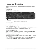
Card Overview
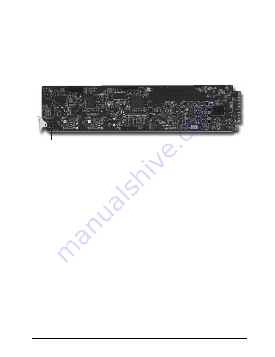
is an example of a MUX-8258 card.
Figure 1.1 MUX-8258 — Card-edge Components
Bootload Button (SW1)
SW1
is used for factory service in the unlikely event of a complete card failure. Do not press this button unless
instructed to do so by Ross Technical Support personnel.
Function Selection Switch (SW2), not shown
On legacy MUX-8258 series cards,
SW2
works in conjunction with the Mode Select Switch (
SW3
) to select general
functions and menu items. Refer to the chapter “
” on page 41 for details.
Mode Select Switch (SW3), not shown
On legacy MUX-8258 series cards,
SW3
is used to enable, disable, and select specific configuration within the
operational function mode menus. Refer to the chapter “
” on page 41 for details.
Control and Monitoring Features
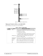
This section provides information on the card-edge LEDs for the MUX-8258. Refer to
of the LEDs and controls.
Legacy MUX-8258 series cards will include a card-edge 4-character display and the
SW2
and
SW3
switches.
Refer to the chapter “
” on page 41 for details on this card-edge menu system.
Bootload Button
Summary of Contents for MUX-8258 Series
Page 1: ...MUX 8258 Series User Guide...
Page 6: ......
Page 14: ...14 Before You Begin MUX 8258 Series User Guide v9 0...
Page 28: ...28 Configuration MUX 8258 Series User Guide v9 0...
Page 30: ...30 Software Upgrades MUX 8258 Series User Guide v9 0...
Page 46: ...46 Card edge Menus MUX 8258 Series User Guide v9 0...


