www.rosscontrols.com
5
© 2021,
ROSS
CONTROLS
®
.
All Rights Reserved.
RSe Series Operating Instructions
2.1.5. Foreseeable Misuse
WARNING
Risk of Injury!
Misuse may result in injury or damage.
f
The product must be used exclusively as intended.
Foreseeable misuse includes:
• Use outdoors
• Bypassing the safety function or diagnostics
• Failing to utilize the onboard sensors to verify valve operation on every cycle –
energizing and de-energizing
• Allowing continued operation of the valve when one or both valve shifted signals
(from position sensors) are not confirmed.
• Operation in low-demand mode per IEC 61508
• Operating at pressures below minimum operating pressure or above maximum
operating pressure.
2.3. Responsibilities of the System Owner
•
Observe the information on assembly and operating conditions listed in the
operating instructions, integration guide, or the data sheet.
• Comply with the further requirements of ISO 13849 (e. g., CCF, DC, PLr, software)
if you intend to use the product in higher categories (2 to 4).
• Make sure that the maximum number of switching cycles (B
10D
) within the service
life T
M
is not exceeded. If the expected number of switching cycles for a component
exceeds the B
10D
value during its period of use, suitable replacement intervals
have to be specified.
• Switch the valve at least once a month to ensure its proper operation.
• Make sure that the fundamental and proven safety principles in accordance with
ISO 13849 for implementation and operation of the component are complied with.
• Make sure that the permissible switch-on and switch-off pulses for feedback-free
operation of the pneumatic devices are observed.
• If you operate the RSe Series valve together with an electric two-hand control, it
must comply with the ISO 13851 standard. Selection and installation of this two-
hand control must take place in accordance with the manufacturer’s specifications.
2.4. Safety Instructions
•
When implementing surge suppression measures, be sure to check whether or
not this extends the valve shut off response time which could extend the machine
stopping time.
• In case of high levels of machine vibration, use appropriate vibration-reducing
elements when installing the valve.
• Supply the proper voltage as overvoltage situations can result in solenoid burnout.
• Make sure that the silencer’s flow capacity is not restricted as this could affect
system performance.
• If required, replace the silencer with a model equivalent or higher in specifications
as ROSS
®
silencers.
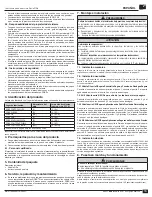
3. Product Identification
Date of manufacture and site of manufacture are permanently stamped:
Manufacturing site
Site abbreviation
Valve printing
(example May 2016)
ROSS CONTROLS USA
(L)
(5 16 L)
ROSS EUROPA
(G)
(5 16 G)
ROSS UK
(RB)
(5 16 RB)
ROSS ASIA
(J)
(5 16 J)
ROSS SOUTH AMERICA
(B)
(5 16 B)
ROSS CONTROLS CHINA
(C)
(5 16 C)
ROSS CONTROLS INDIA
(RCI)
(5 16 RCI)
See back page for ROSS addresses.
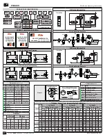
Product label identification & product key identification example, see page 2.
4. Prerequisites for Use of the Product
f
Make these operating instructions available to the engineer and assembly
technician of the machine/system in which the product will be used.
f
Keep these operating instructions for the entire product life cycle.
4.1. Qualified Personnel
Assembly, installation, commissioning, maintenance, and decommissioning should
only be carried out by qualified personnel that have the required knowledge of and
experience in dealing with electrical and pneumatic control technology.
5. Package Contents
Items included:
•
RSe valve •
•
Operating instructions
6. Service, Repair, and Maintenance
f
In case of technical problems or a required repair, please contact your local ROSS
®
representative. If used properly, the RSe valves will not require maintenance.
Unless otherwise required, ROSS
®
recommends performing a functional test at
least once a month (see 8.1 Test Procedure).
7. Assembly and Installation
CAUTIONS
Risk of injury due to installation while pressurized or with live parts!
Installation while pressurized or with electrical power switched on can result in injuries
due to sudden pressure build-up or electric shock.
f
De-energize and de-pressurize the relevant system parts before installing the valves.
f
Secure the system to prevent it being switched back on again.
ATTENTION
Destruction of components!
Chemical substances can damage the surface, the markings and the seals of the device.
f
Install the valve such that it is protected against the effects of chemicals.
Damage to the device through storage at incorrect temperatures!
The storage temperature represents the permissible ambient temperature and depends on
the type of valve in question.
f
Observe the temperature information in chapter 10 “Technical Data.”
7.1. Mechanical Installation
Secure the valve using the through holes in the valve base. Refer to pattern for the
required dimensions, see dimensional drawings on page 2.
7.2. Pneumatic Installation
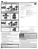
7.2.1 3/2 RSe Series Valve for Safe Supply and Safe Exhaust Function
Connect the compressed air supply to port 1, connect port 2 to the downstream portion
of the circuit, port 3 is the exhaust port
7.2.2 5/2 RSe Series Valve for Safe Return Cylinder/Actuator
Connect the compressed air supply to port 1, connect ports 2 & 4 to the the pneumatic
actuator, port 3 and 5 are the exhaust ports
7.2.3 5/2 RSe Series Valve for Safe Return Dual Pressure Application
Convert to external pilot supply (see Integration Guide), supply pressure in the
recommended pressure range to the EPS port. The normal exhaust ports will
become the new inlets with pressure 1 on port 5 and pressure 2 on port 3, connect
port 4 (pressure 1) & 2 (pressure 2) to the the pneumatic actuator. Port 1 is the
exhaust port.
7.2.4 5/2 RSe Series Valve for Safe Pressure Select Application
Convert to external pilot supply (see Integration Guide), supply pressure in the
recommended pressure range to the EPS port. and the normal exhaust ports (3 and
5) must be plugged. The normal work ports will become the new inlets with pressure 1
(high) on port 4 and pressure 2 (low) on port 2. Port 1 will be used as the outlet port. A
self relieve pressure regulator at the port with the lower pressure maybe useful.
7.3. Electrical Installation
Electrical connections to the solenoids are made with EN 175301-803 Form C
receptacles on the valve. Electrical connections to the sensors are made with male
M8 receptacles on the valve. See Pinouts on page 2. Female connectors and cables
are sold separately. The cables and cable connections as well as the electrical control
for the double valves must comply with the applicable safety regulations.
8. Commissioning and Operation
CAUTIONS
Damage to health due to loud noise!
Levels above 70 dB(A) may lead to damage to health!
f
Always wear ear protectors when working on the product.
Before commissioning, the installation has to be carefully inspected by a qualified,
trained professional.
Make sure that the technical specifications matches the operating criteria of the
machine and/or the pneumatic system.
Always set the compressed air supply to a level that ensures that the minimum
operating pressure is adhered to (see section 10 Technical Specifications).
ENGLISH

