6
www.rosscontrols.com
© 2021,
ROSS
CONTROLS
®
.
All Rights Reserved.
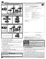
8.1. Test Procedure
8.1.1
3/2 Valves
1. Solenoid A energized – Valve is faulted, supply is shut off, downstream air exhausts
through port 3. Sensor A voltage is off, sensor B is on.
2. Reset valve by de-energizing both solenoids – Valve is off, supply is shut off, and
downstream air is exhausted through port 3. Sensors A & B are high.
3. Solenoid B energized – Valve is faulted, supply is shut off, downstream air exhausts
through port 3. Sensor A is on, sensor B is off.
4. Reset valve by de-energizing both solenoids – Valve is off, supply is shut off, and
downstream air is exhausted through port 3. Sensors A & B are on.
5. Solenoids A & B energized – Valve is on, air pressure is supplied downstream
through port 2, port 3 is shut off. Sensors A & B are off.
6. Solenoids A & B de-energized – Valve is off, supply is shut off, and downstream air
is exhausted through port 3. Sensors A & B are on.
8.1.2 5/2 Valves for Safe Return Cylinder/Actuator Application
1. Solenoid A energized – Valve is faulted, port 2 is pressurized, port 4 is exhausted
through
port 5. Sensor A is off, sensor B is on.
2. Reset valve by de-energizing both solenoids – Valve is off, port 2 is pressurized,
port 4 is exhausted through port 5. Sensors A & B are on.
3. Solenoid B energized – Valve is faulted, port 2 is pressurized, port 4 is exhausted
through port 5. Sensor A is on, sensor B is off.
4. Reset valve by de-energizing both solenoids – Valve is off, port 2 is pressurized,
port 4 is exhausted through port 5. Sensors A & B are on.
5. Solenoids A & B energized – Valve is on, port 4 is pressurized, port 2 is exhausted
through port 3. Sensors A & B are off.
6. Solenoids A & B de-energized – Valve is off, port 2 is pressurized, port 4 is
exhausted through port 5. Sensors A & B are on.
8.1.3 5/2 Valve for Safe Return Dual Pressure Application
1. Solenoid A energized – Valve is faulted, port 4 is pressurized, port 2 is exhausted
through port 1. Sensor A is off, sensor B is on.
2. Reset valve by de-energizing both solenoids – Valve is off, port 4 is pressurized,
port 2 is exhausted through port 1. Sensors A & B are on.
3. Solenoid B energized – Valve is faulted, port 4 is pressurized, port 2 is exhausted
through port 1. Sensor A is on, sensor B is off.
4. Reset valve by de-energizing both solenoids – Valve is off, port 4 is pressurized, port
2 is exhausted through port 1. Sensors A & B are on.
5. Solenoids A & B energized – Valve is on, port 2 is pressurized, port 4 is exhausted
through port 1. Sensors A & B are off.
6. Solenoids A & B de-energized – Valve is off, port 4 is pressurized, port 2 is
exhausted through port 1. Sensors A & B are on.
8.1.4 5/2 Valve for Safe Pressure Select Application
1. Solenoid A energized – air pressure is supplied from port 2 downstream through
port 1, pressure supply from port 4 to 1 is shut off. Sensor A is off, sensor B is on.
2. Reset valve by de-energizing both solenoids – air pressure is supplied from port 2
downstream through port 1, pressure supply from port 4 to 1 is shut off. Sensors A
& B are on.
3. Solenoid B energized – air pressure is supplied from port 2 downstream through
port 1, pressure supply from port 4 to 1 is shut off. Sensor A is on, sensor B is off.
4. Reset valve by de-energizing both solenoids – air pressure is supplied from port 2
downstream through port 1, pressure supply from port 4 to 1 is shut off. Sensors A
& B are on.
5. Solenoids A & B energized – air pressure is supplied from port 4 downstream
through port 1, pressure supply from port 2 to 1 is shut off. Sensors A & B are off.
6. Solenoids A & B de-energized – air pressure is supplied from port 2 downstream
through port 1, pressure supply from port 4 to 1 is shut off. Sensors A & B are on.
Results from the test procedure other than those listed above could indicate a valve
malfunction. See section 5, Service, Repair, and Maintenance.
Failure of the valve to shift synchronously leads to a fault in the RSe Series valve.
This could happen for a variety of reasons, such as:
• Defective piston seals,
• Main valve elements experiencing a switching delay due to dirt or resinous oil,
• Insufficient electrical signals to valve solenoids; suitable voltage not available,
• Receipt of signals at solenoids not synchronous,
• Pilot valves experiencing a switching delay due to damaged components, dirt, or
resinous oil,
• Excessive water build-up in the valve.
9. Disconnecting and Removal
CAUTIONS
Risk of injury due to disconnecting pressurized or live parts.
f
Disconnecting a pneumatic component while the system is pressurized or while
electrical power is supplied can result in injury or death due to sudden pressure
release, unexpected movement, or electric shock.
f
Isolate and lock out the electrical and pneumatic systems before disconnecting the
valves.
10. Technical Specifications
Design:
Redundant 5/2 (or 3/2) directional valve elements of spool construction.
(3/2 function is Normally Closed.)
Actuation:
Solenoid pilot operated with spring return. One solenoid per valve element
– both to be operated synchronously.
Flow Media:
Compressed air (neutral gases) according to ISO 8573-1 Class 7:4:4.
Operating Pressure Range:
43 to 145 psig (3 to 10 bar) with internal pilot supply.
0 to 145 psig (0 to 10 bar) with external pilot supply.
External Pilot Supply Pressure:
43 to 145 psig (3 to 10 bar).
Ambient/Media Temperature:
40° to 120°F (4° to 50°C).
SAFETY CLASSIFICATION:
Directives:
2006/42/EC (Machinery Directive) 2004/108/EC (EMC directive)
Standards:
ISO 13849-1, IEC61508/IEC62061, DIN EN 61326-3-1.
Test Principle:
GS-IFA-M07, April 2017.
Safety Functions:
“Safe exhaust” and “protection against unexpected start-up”, “safe
return”, and “safe pressure select” and “safe return dual pressure” applications.
Vibration resistance (DIN EN 60068-2-6):
0.35 mm ± 0.05 mm displacement at 10
Hz–55 Hz.
Shock Resistance (DIN EN 60068-2-27):
30 g with 18 ms duration.
Shock Wave Form:
Sinus half-wave.
Safety Classification:
Max. category 4, PL e, SIL 3.
Mean Time to Dangerous Failure:
See B
10D
from the ROSS SISTEMA library.
Common Cause Failure – CCF:
> 65.
Diagnostic Coverage (DC):
High, 99%.
Minimum Operation Frequency:
1 x per month, to ensure proper function.
Maximum Cycle Rate:
2 Hz.
Mounting Orientation:
Any, preferably vertical.
Monitoring:
Dynamic, cyclical, external with customer supplied equipment. Monitoring
should check state of both valve position sensors with any and all changes in state of valve
control signals.
Solenoids:
Per VDE 0580. Rated for continuous duty. Electrical connection according
to EN 175301-803 Form C. Enclosure rating according to DIN 400 50 IP 65.
Proximity Sensors (
2 per valve)
:
PNP.
Standard Voltage:
24 volts DC.
Supply Voltage:
For CSA/UL compliance, in DC applications the valve must be
connected to a NEC Class 2 power supply.
B10
D
Value According to ISO 13849-1 and -2:
Service life parameter measured
according to ROSS Engineering Standard, Laboratory Test Procedures Section 8:
G1/8: B
10D
= 20 million cycles.
G1/4: B
10D
= 20 million cycles.
G1/2: B
10D
= 20 million cycles.
Proximity Sensors:
T
10D
= 20 years.
Sound Pressure Level [dB(A)]:
The sound pressure level is influenced by the
individual systems used for reduction of noise emissions. Use only silencers with
exhaust flow capability greater than the exhaust capability of the RSe Series valve,
e.g., do not restrict the valve exhaust. The RSe Series valve is sold without silencer.
Use of the product without the silencer is not recommended.
Flow Rates:
See page 2.
Power Consumption (each solenoid):
1.5 Watts per solenoid (2).
Current Consumption (each sensor):
<23mA.
Maximum Recommended Allowable Discordance Time:
250 msec.
11. Disposal
Dispose of the valve in accordance with the applicable statutory regulations in your
country.
RSe Series Operating Instructions
ENGLISH

