www.rosscontrols.com 3
3/2 RSe Series Safe Exhaust Double Valves Integration Guide
Introduction
ROSS Controls offers a variety of safety valves for use in various safety functions such as safe exhaust, safe cylinder return, and safe
load holding/stop. This document focuses specifically on ROSS Controls’ 3/2 RSe Series valves that are used for safe pneumatic exhaust
functions and utilize magnetic proximity sensors (PNP) to provide feedback to a safety control system for external monitoring.
Pulse Testing
In dual channel safety circuits, pulse testing is a method utilized to detect fault conditions that, otherwise, may be undetected. Pulse testing
of the solenoids is required in dual channel circuits in order to reach Performance Level e (PL e). However, pulse testing of the feedback
sensors is not required. Pulse testing of the solenoids will not affect the performance of the ROSS 3/2 RSe valve.
There are two methods of pulse testing outputs. The most common method is to use the native pulse testing instruction embedded by
the manufacturer in Safety PLCs and Safety Relays. The other method is to use custom programming code generated by the user. We
recommend the use of native pulse testing instructions of the respective manufacturers’ Safety PLCs or Safety Relays because these
instructions are fixed and cannot be tampered with. These instructions typically have a pulse period (cycle) of 400 ms to 600 ms and a
pulse width of 0.4 ms to 0.8 ms. Pulse testing the outputs to the solenoids on the RSe valve at this frequency and duration does not affect
the performance of the valve but does provide a method to monitor for the occurrence of wiring faults in the output portion of the safety
circuit controlling the valve solenoids.
Exhaust Times and Faulted Flow Rates
When designing a safety circuit, the machine stopping time is a critical factor that determines the placement of guarding solutions. One
factor in safe distance calculations is the exhaust time of the valve that is responsible for isolating and dumping the pneumatic energy from
the machine. The faster your valve exhausts, the quicker the machine can stop and the closer your safety devices may be placed to the
hazardous area. This can improve overall operating efficiency, and possibly allow the footprint of the machine to be smaller.
Even more important than exhaust time is the “Faulted exhaust flow rate.” Faulted exhaust flow rate is the exhaust rate of the valve in
its worst state. Double valves (redundant valve systems used for safety applications) will not exhaust quite as quickly when there is an
internal fault condition in the valve, such as when one of the redundant valve components is actuated and the other one is not actuated.
For this reason, double valves used in safety circuits should always be sized using faulted flow rates as the worst case condition.
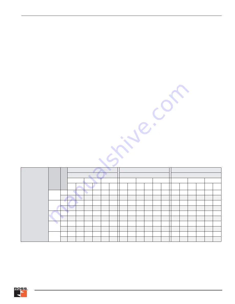
The chart below shows the RSe valve’s faulted exhaust flow times at various downstream volumes and operating pressures.
Exhaust Time –
Normal and Faulted
Conditions (s)
Volume
ft
3
(L)
Normal or F
aulted
Port Size 1/8
Port Size 1/4
Port Size 1/2
Operating Pressure psig (bar)
Operating Pressure psig (bar)
Operating Pressure psig (bar)
30 (2)
90 (6)
145 (10)
30 (2)
90 (6)
145 (10)
30 (2)
90 (6)
145 (10)
to
15 (1)
to
7 (0.5)
to
15 (1)
to
7 (0.5)
to
15 (1)
to
7 (0.5)
to
15 (1)
to
7 (0.5)
to
15 (1)
to
7 (0.5)
to
15 (1)
to
7 (0.5)
to
15 (1)
to
7 (0.5)
to
15 (1)
to
7 (0.5)
to
15 (1)
to
7 (0.5)
0.071 (2)
N
0.212 0.319 0.391 0.506 0.578 0.698
0.159 0.218 0.290 0.354 0.420 0.493
0.184 0.219 0.290 0.321 0.395 0.430
F
0.250 0.358 0.432 0.547 0.597 0.715
0.197 0.272 0.361 0.445 0.476 0.560
0.197 0.231 0.316 0.351 0.446 0.488
0.35
(10)
N
0.871 1.418 1.704 2.257 2.545 3.073
0.574 0.854 1.098 1.392 1.679 2.007
0.392 0.561 0.658 0.810 1.003 1.165
F
1.084 1.602 1.897 2.451 2.590 3.114
0.775 1.135 1.461 1.851 1.892 2.294
0.407 0.574 0.744 0.901 1.228 1.429
0.71 (20)
N
1.695 2.792 3.344 4.447 5.005 6.043
1.094 1.649 2.108 2.689 3.253 3.901
0.652 0.989 1.119 1.421 1.763 2.083
F
2.126 3.158 3.729 4.831 5.082 6.113
1.494 2.213 2.836 3.609 3.662 4.462
0.669 1.001 1.280 1.587 2.205 2.605
1.41 (40)
N
3.344 5.539 6.625 8.826 9.924 11.982
2.132 3.239 4.127 5.284 6.400 7.687
1.171 1.845 2.039 2.642 3.284 3.920
F
4.211 6.269 7.391 9.591 10.066 12.110
2.942 4.370 5.586 7.125 7.203 8.798
1.193 1.857 2.350 2.961 4.161 4.957
5.30 (150)
N
12.410 20.651 24.670 32.911 36.980 44.647
7.845 11.983 15.233 19.554 23.710 28.515
4.027 6.552 7.104 9.360 11.645 14.022
F
15.676 23.380 27.537 35.771 37.475 45.096
10.888 16.232 20.712 26.465 26.677 32.643
4.075 6.564 8.238 10.514 14.915 17.896

