background image


© 2021,  

ROSS

 CONTROLS

®

.  

All Rights Reserved.

3/2 RSe Series Safe Exhaust Double Valves Integration Guide

RSe Wiring (Pinouts)

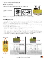
The RSe wiring connections are made via EN175301-803, Form C receptacles for 
the solenoids and male M8 receptacles on the sensors.  Pinouts are shown below.

Solenoids & Position Sensors 
Pinouts

NOTE:

  The sensors must be wired with 24 volt (+) and 0 volt (-) connections in parallel with each other.  

GRN/YEL

GROUND

BROWN

BLUE

GRN/YEL

Solenoid Cables with 

EN Connector

GRN/YEL

GROUND

3

2

1

4

BLUE

PIN 2

BROWN

PIN 1

Sensor Wiring M8 Connector

1

3

4

1

3

4

L+

L-

1  Brown

3  Blue

4  Black

Wire Colors

Pilot Supply Conversion

The RSe Series valve comes from the factory configured for internal pilot supply, which sources pilot supply air pressure internally 
from port 1 in the valve sub-base. However, the valve can be converted in the field to operate with external pilot supply through 
the EPS port in the valve sub-base. When this conversion to external pilot supply is made, the valve solenoid pilots will get their 
supply air from a source that is independent of the supply line connected to Port 1. 
External pilot supply is typically used in applications where the normal supply pressure may be lower than the minimum operating 
pressure of the valve (45 psig (3 bar)). 
In order to convert the RSe valve to external pilot supply: 
A.  Shut off and exhaust all pressure from the system and disconnect all electrical power from the valve.
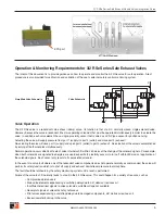
B.  Remove the valve  from the sub-base (4 screws). See photo below. 
C.  Remove the set screw from the external pilot supply port in the top of the base.  See figures below.
D.  Install the set screw in the internal pilot supply port in the top of the sub-base (max. torque 49 in-lbs (5.5 Nm).  See figures below.
E.  Install an external pilot supply line into the EPS port in the side of the sub-base. The source for this external pilot supply should
  supply a constant supply of air with pressure greater than or equal to the supply pressure in Port 1; 45 psig (3 bar) minimum.
F.  Re-install the valve on the sub-base (4 screws - max. torque 49 in-lbs (5.5 Nm)). See photo below. 

Solenoids

Sensors

EPS port

EPS port

Mounting Screws

Mounting Screws

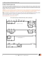
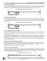
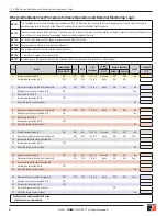
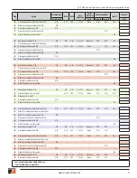
Summary of Contents for RSe Series

Page 1: ...Integration Guide RSe Series Safe Exhaust Double Valves...

Page 2: ...ion and External Monitoring Logic 8 10 Cautions Warnings and Standard Warranty Cover Global Locations Disclaimer Sample Logic and any and all related diagrams contained in ROSS Controls Integration gu...

Page 3: ...ed to the hazardous area This can improve overall operating efficiency and possibly allow the footprint of the machine to be smaller Even more important than exhaust time is the Faulted exhaust flow r...

Page 4: ...de the valve solenoid pilots will get their supply air from a source that is independent of the supply line connected to Port 1 External pilot supply is typically used in applications where the normal...

Page 5: ...eously Normal operation occurs when both sets of valve internals shift within 250 msec of the change of the solenoid signals For example when both solenoids are signaled to energize we would expect bo...

Page 6: ...n the event of a stop signal from any safety system input the safety system should immediately shut off the safety controller outputs to the valve solenoids as required by the application regardless o...

Page 7: ...r transducer is added upstream of the valve in port 1 Loss of supply pressure while actuated should cause both valves to de actuate due to lack of pilot pressure thus causing both sensors to switch on...

Page 8: ...t 2 Sensor A Sensor B P F 1 Energize solenoids A B ON ON ON 1 to 2 3 Pressure OFF OFF No 2 De energize solenoids A B OFF OFF OFF 1 2 to 3 None ON ON 3 Disconnect solenoid cable from solenoid B OFF OFF...

Page 9: ...sure OFF OFF No 48 Remove supply air from port 1 OFF OFF 1 2 to 3 None ON ON Yes 49 Resupply air to port 1 50 De energize solenoids A B OFF 51 Reset the safety control system No 52 Disconnect sensor c...

Page 10: ...70 Attempt to energize solenoids A B ON 71 Attempt to reset the safety control system 72 De energize solenoids A B OFF 73 Reset the safety control system No 74 Energize solenoids A B ON ON ON 1 to 2...

Page 11: ...etc are present in virtually every air system Although some valves are more tolerant of these contaminants than others best performance will be realized if a filter is installed to clean the air suppl...

Page 12: ...0 1 49 45 65 65 www rossfrance com Germany ROSS EUROPA Tel 49 0 6103 7597 100 www rosseuropa com manufactIS Tel 49 0 2013 16843 0 www manufactis net United Kingdom ROSS PNEUMATROL Tel 44 0 1254 87227...

Reviews: