www.rosscontrols.com 5
3/2 RSe Series Safe Exhaust Double Valves Integration Guide
Operation & Monitoring Requirements for 3/2 RSe Series Safe Exhaust Valves
The intent of this document is to provide guidance on how to operate and monitor the 3/2 RSe valve for safe operation. A test
procedure is also provided for verification and validation of the user’s external safety control monitoring system.
Valve Operation
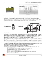
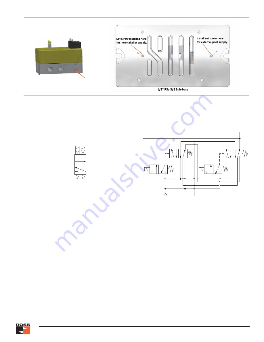
The 3/2 RSe valve is a redundant safe exhaust (dump) valve. Its function is that of a 3/2, normally closed, single-solenoid valve.
However, because the valve is redundant it has two operating solenoids that must be operated simultaneously in order to actuate the
valve. In addition each valve element has a single, proximity sensor that is wired as a PNP type sensor for position sensing.
Actuating the valve will supply pressure from port 1 (supply) to port 2 (outlet) and close port 3 (exhaust).
De-actuating the valve will close port 1 (supply) and open port 2 (outlet) to port 3 (exhaust). De-actuation of the valve is accomplished
by turning off both solenoids simultaneously.
Normal operation occurs when both sets of valve internals shift within 250 msec of the change of the solenoid signals. For example,
when both solenoids are signaled to energize, we would expect both proximity sensors to turn off within 250 msec of application of
the solenoid signals. Each sensor only reacts to its associated solenoid.
In the event of a valve fault where one of the redundant valve components does not operate normally, as commanded, the valve will
perform its safety function which is to shut off supply and exhaust downstream pressure to atmosphere.
The fault should be latched in by the safety monitoring system until a reset is performed.
Failure of the valve to shift normally leads to a fault in the 3/2 RSe valve. This could happen for a variety of reasons, such as:
• Compromised piston seals
• Main valve elements experiencing a switching delay due to dirt, debris or resinous oil
• Insufficient electrical signals to valve solenoids; suitable voltage not available
• Receipt of signals at solenoids not synchronous
• Pilot valves experiencing a switching delay due to damaged components, dirt, debris or resinous oil
• Excessive water build-up in the valve
EPS port
Simplified Valve Schematic
1
3
2
Valve Schematic
2
2
4
5 1 3
2
2
1
3
4
5 1 3
2
2
1
3
3
1

