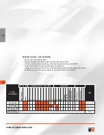
IMPORTANT NOTE:
Please read carefully and thoroughly all of the
CAUTIONS, WARNINGS
on the inside back cover.
F2.3
www.rosscontrols.com
Online Version
Rev. 11/14/16
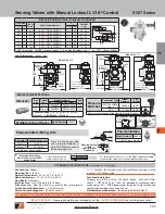
Sensing Valves, Air Dump/Release
SV27 Series
2-Way 2-Position Valves, Solenoid Pilot Controlled
Port Size
1, 2
Body
Size
Valve Model Number
*
C
V
1-2
Weight
lb (kg)
1/2
3/4
SV27
N
C105407PSAA
**
7.7
4.6 (2.1)
3/4
3/4
SV27
N
C105507PSAA
**
9.0
4.6 (2.1)
1
3/4
SV27
N
C105607PSAA
**
9.0
4.6 (2.1)
1
1
1/4
SV27
N
C107607PSAA
**
24
8.1 (3.7)
1
1/4
1
1/4
SV27
N
C107707PSAA
**
29
8.1 (3.7)
1
1/2
1
1/4
SV27
N
C107807PSAA
**
29
8.1 (3.7)
2
1
PV
12
*
NPT port threads. For BSPP threads, replace “
N
” in the model number with a “
D
”, e.g., SV27
D
C105407PSAA1A.
**
Insert voltage code: “
1A
”=110-120 volts, 50/60 Hz; “
1D
”= 24 volts DC; .e.g., SV27NC105407PSAA
1A
. For other voltages, consult ROSS.
Construction:
Poppet.
Mounting Type:
In-Line.
Solenoid Pilot:
AC or DC power. Rated for continuous duty.
Standard Voltages:
24 volts DC; 110-120 volts AC, 50/60 Hz.
Power Consumption:
87 VA inrush, 30 VA holding on 50 or 60 Hz; 14
watts on DC.
Ambient Temperature:
40° to 120°F (4° to 50°C).
Media Temperature:
40° to 175°F (4° to 80°C).
Flow Media:
Filtered air.
Inlet Pressure:
40 to 150 psig (2.8 to 10.3 bar).
Pilot Pressure:
Must be equal to or greater than inlet pressure.
Switch Current/Voltage Max.:
2.5 A/120 volts AC.
Switch Current/Voltage Min.:
50 mA/24 volts DC.
NOTE:
Electrical life of switch varies with conditions and voltage; rated
in excess of 15 million cycles.
Functional Safety Data:
Category 2 PL d; B10d: Valve - 20,000,000, Switch – 2,000,000; PFHd:
2.35x10
-7
; MTTFd: 98.15 (n
op
: 7360); DC (obtained by monitoring safety
switch status): 90%; ROSS recommends testing the switch function and
sealing for load holding valves every 8 hours.
Vibration/Impact Resistance:
Calculated to BS EN 60068-2-27.
STANDARD SPECIFICATIONS
(for valves on this page)
:
2X Ø
0.34 (8.0)
Port 1 (inlet)
{Port 2 (outlet)
on opposite
side}
6.49 (165)
4.66 (118)
4.48
(114)
3.09
(78)
4.09 (104)
1.10
(28)
1.78
(45)
1/8 Pilot
exhaust
port Y-3
1/2 Electrical
conduit port
1.26
(32)
1/8 External pilot
supply port X
12.0
(303)
5-pin M12
connector
Port PV
(pressure
verification)
Port Y-3
(pilot exhaust)
Port PV
(pressure
verification)
9.3
(235)
3-pin
Mini connector
2X Ø
0.34 (8.0)
Port X-1
(1/8 external
pilot supply)
3.25 (83)
4.45 (113)
2.74
(69)
1.80
(46)
3.15 (18)
1.53
(39)
0.60
(15)
5.7 (145)
Port 1(inlet)
[Port 2 (outlet
on opposite site]
5-pin M12
connector
Integrated Double-Pole
Single-Throw Switch (DPST)
Switch States
Contact conditions during
switch travel (0 to 6 mm).
For valves basic size 3/4 & 1-1/4
, the DPST switch is actuated
whenever the valve is not in the normal home position.
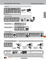
Kit Number
*
Length meters
(feet)
2239H77
4 (13.1)
2240H77
10 (32.8)
*
Cable has one connector.
Sensing Switch
Cable
with 5-pin M12
Connector
BRN
PIN 3
BLUE
PIN 2
GRN/YEL
(GROUND)
PIN 1
BRN
BLUE
GRN/YEL
Solenoid Cable
with 3-pin MINI
Connector
A
CCessories
& o
ptions
Body Size 3/4
Body Size
1
1/4
BRN
PIN 1
BLUE
PIN 3
BLK
PIN 4
GRY
PIN 5
WHT
PIN 2
BLUE
BRN
BLK
WHT
GRN/YEL
Current/Voltage Max. 2.5 A /120 VAC
Preassembled Wiring Kits
These kits include two cables with a
cord grip on each cable. One cable has
a 3-pin MINI connector for the solenoid,
and one has a 5-pin M12 (Micro)
connector for the sensing switch.
F
F2
Indicator Light Kit
Kit Number
24 volts DC 110-120 volts AC 50-60 Hz
862K87-W
862K87-Z
Valve Dimensions –
inches (mm)
Pressure
Switches
Connection Type Model Number
*
Port Threads
EN 175301-803
Form A
586A86
1/8 NPT
M12
1153A30
1/8 NPT
*
Pressure switch closes on falling pressure of 5 psig (0.34 bar).
Manual Override Kits
BUTTON Type
Locking Type Model Number
*
FLUSH
Non-Locking
790K87
Locking
792K87
EXTENDED
Non-Locking
791K87
EXTENDED with
PALM
Non-Locking
984H87
Pop-Up
Indicator
Model Number
**
988A30
**
1/8 NPT port threads
.
3
1
2
Normally
Closed
Normally Open
Ground
Common
EN Connector Pinout
Pin 1
Common
Pin 3
Not Used
Pin 2
Normally
Closed
Pin 4
Normally
Open
M12 Connector Pinout


