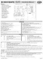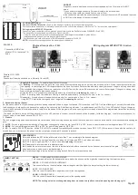
GND/ANT
Frequency reception antenna, connects the strpped part of the 16cm wire to the ANT
borne.
If you need more range, connect a 2m coaxial cable to the antenna input.
- At the top of the cable you should find the core at 16cm.
In the connection part with the control board you must put the core in ANT borne and the mesh
in GND, as in the design of the control panel.
CLOSING PHOTOCELL
Photocell FAIL SAFE function.
(Dip 6 to ON) with each operating cycle the photocell is checked.
Photocell must be switched on in Normally Closed (NF) mode, connect the photocell 's GND to the "TX-" borner of the control panel.
Wiring diagram WITHOUT FS function
Connection mode compatible with the previous central units or with the Fail Safe function DISABLED (Dip 6 OFF)
The photocell must be switched on in Normally Open mode (NO)
- It must be at the same height and in the same alignment, ideal height for installation in gates is 50cm.
- Installation should be done as close as possible to the gate.
- Certification is only valid with the use of ROSSI approved photocells: SIA 30 FS
NOTE:
In the path recognition process, the barrier sensor is disabled.
SIA 30 FS.
- Connect the GND of the
photocell TX to the central TX-
borne
Photocell connection - FAIL
SAFE
Wiring diagram WITHOUT FS function
Set the DIP 6
to ON
Photocell FAIL SAFE
function.
TX- 12v
GND12v CM NF
GND12v
GND12v CM NA
The photocell must be switched on in Normally Closed (NF)
Enable DIP functions
- To enable the switch to ON position
1- Building -
All controls open the gate, that only closes by automatic closing, which will only stop at the open limit, if there is another control during
the opening, central will ignore. After the gate reaches the open limit switch it will start the automatic closing time count, the gate will only close after
the scheduled time elapses. If there is a remote control or BOT switch, the time will be reset and the count will start again. If the gate is closing, any
control will make the gate stop and open again.
Using the BOT F it is possible to close the gate before the break time after
releasing
the contact.
(Note: In building mode the automatic closing is enabled automatically, just adjust the time in the 1st control.)
Residential - Accepts all control and switch commands (1st - control opens, 2nd - to, 3rd - closes).
Using BOT F it is possible to stop and close the gate after
releasing
the contact.
2 - Automatic closing (Pause)
Set the pause switch to ON position and give the opening command. When the open limit switch (FA) is reached, the ST LED will start flashing in 1-second intervals, allow
the desired time to elapse for the pause value and give the control again. Each flashing indicates 1 second elapsed until 12h (E.g. If the LED blinks 20 times, the pause
time will be 20 seconds. After this operation is completed, the pause will be programmed, every opening that occurs and elapses in the programmed time will automatically
close the gate.)
To disable this feature, simply put the pause switch in the OFF position. In the next control the pause will be disabled. (for this setting type, it is of utmost importance, for
the user safety, to use barrier sensors 'SIA 30 FS'.)
3 - Closure
The lock programming when enabled causes the control panel, after receiving an opening control, first send a pulse to open the lock and after a few seconds starts opening the
gate.
4 - LV/PS
- For use in gates considered to be of low weight, consequently of less inertia, leave DIP 4 in OFF, for use in heavier and more inertia gates, leave DIP 4 in ON.
5 - DZ/BV
- For use in sliding gates leave DIP 5 in OFF, for use in Tilting gates let DIP 5 ON.
6 - FS
- To enable FAIL SAFE function, set the DIP to ON; To maintain compatibility with previous versions, leave DIP 6 OFF (If this process is done with the central unit
switched on, you must remove the power from the control panel and wait 10 seconds to restart)
ADJUSTMENTS
Press and release the SET button at intervals of less than 1 sec. according to the desired program.
1x
- BOT A works as "open-close" exactly as on today's KXH cards and BOT F only stops and closes.
2x
- BOT A only to open, and BOT_F only to close after
releasing
the contact.
3x
- Disables auto-reverse mode in residential mode
4x
- Enables the auto reverse mode of the lock in residential mode, after a command by the button or remote control the gate
stops and returns to open even in residential mode.
9x
- Set all the settings to factory default, including default. Note: Do not erase the controls.
TRIMPOT SETTING
DECEL.
- DECELERATION ADJUSTMENT
This command will act on the deceleration ramp before the stroke end (the higher the trimpot setting, the lower the ramp).
9
ACCEL.
- ACCELERATION ADJUSTMENT
This control will act on the acceleration ramp at the gate start (the higher the trimpot setting, the lower the ramp).
VL.FC
- CLOSING SPEED
With this control it is possible to separately control the closing speed
VL.AB
- OPENING SPEED
With this control it is possible to separately control the opening speed
NOTE: The setting value is not changed during door movement, only after a complete opening and closing cycle.
Page02
8
ADJUST.
5
central antenna
16cm
6
7
C
oax
ial
c
abl
e
up t
o 3M
Core
Mesh
16 cm of core
without mesh
ADJUSTMENTS


