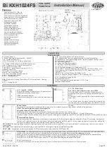
RECORD REMOTE CONTROL
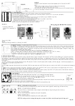
Recording of access key:
•
Press and release the learn button on the control panel;
•
With the
ST
LED lit, pressing one of the control buttons at the end of the recording will blink and go off, indicating that the programming has been accepted.
•
Repeat the process to record other buttons.
Deleting individual buttons:
This feature allows you to erase the encoding from the central memory, regardless of key code, without affecting others. For this, the access key must be in hand to perform this
procedure.
Hold down learn while pressing the key switch you want to delete.
Note
:
This operation can not exceed the maximum time of 5 seconds.
Erase memory
: Press the
LEARN
button and hold until the
ST
LED goes out, with this procedure you delete all recorded codes.
Removable Memory:
This control unit contains a removable memory where it can be replaced or removed in case the control unit is damaged. By inserting the memory IC in another control
panel the recording of the controls remains recorded.
NOTE:
Check the fitting position of the Memory Ci with the serigraphy of the board.
To get the system started, follow the next 4 steps:
1- Gate
Set DIPS 4 and 5 between LV/PS (light/heavy) and DZ/BV (sliding/tilting) according to your application and record a Rossi control at the control panel.
2- Setup
Press and hold the SET button for 5 seconds until the ST LED blinks and releases the button
, then starts the automatic route recognition process at a slow opening
and closing speed.
3- Optimization
After completion of step 2, complete a opening and closing cycle by the remote control, thus completing the process.
4- Regulation
The parameter settings LV/PS, DZ/BV and the trims ACCEL., DECEL., VLFC, VLAB can be done at any time; after the adjustment make a complete opening and closing
cycle by the
remote control
to confirm the setting value, then repeat step 3.
OBS:
(VERY IMPORTANT - READ OUT):
1- Until SETUP step 2 is done, the ST LED will flash slowly and the speed will be reduced.
2 - Make sure that the magnets are positioned "Sensor Hall End of Stroke" on the sliding line or the "Reed Switch End of Switch" on the tilting and pivoting line, properly
identified (FF and FA) before starting the path recognition process ; if you need to move the magnet or Reed, repeat step
2 Setup
.
3 - The "Photocell" safety device will be inoperative in step 1 and 2.
4
- The Tx controls, button or SET button have priority over the path recognition process. Therefore, if any of these devices are triggered during the recognition process, the
system will be interrupted and the process of step
2 SETUP
must be restarted.
5 - In step 2, if the gate is not in the end of stroke, the plate moves the gate to a stroke end and then completes a full opening and closing cycle 6 - If the magnet
has to be repositioned, it will be necessary to redo the path of step
2 SETUP
.
7 - The control unit has a thermal protection feature: if it reaches a temperature higher than 80°, the control panel will stop the current cycle and stop with the
ST LED lit and
FF, FA blinking
until the temperature decreases.
Failure
Cause
Solutions
Doesn't Speed Up
The
ST
LED is flashing
SETUP process.
slowly,
it
was
not
done
th
e
Do the '' Getting Started '' process
Speed trimpot setting VL.FC and VL.AB low.
Set the trimpot levels VL.FC and VL.AB clockwise
Gate is over max. weight or locked
Check the weight limit for the driver and the displacement of
the gate
Engine makes noise
and doesn't move
Motor connected at wrong voltage
Insert voltage according to motor label
The starter capacitor is not connected to the central CAP
borne
Insert starting capacitor according to voltage and motor
power
Doesn't start SETUP, FF or
FA LED blinking
The polarity of the magnet is inverted
Correctly position the FA and FF magnets
Wires V and W are inverted
Reverse the position of wires V and W
The gate is out of the way limit
start the SETUP process with the gate in the middle
of the course
Do not end SETUP
The polarity of the magnet is inverted
Correctly position the FA and FF magnets
Wires V and W are inverted
Reverse the position of wires V and W
The buttons on the remote control, SETUP or LEARN were
pressed before the process was completed.
Start the
finishing
process
of
SETUP
with
out
activati
ng
th
e
button
s
until
Motor does not
turn on: ST LED
off
Motor with power greater than specified.
Check engine power, damaged/wrong capacitor, damaged
motor or broken wire.
Engine does not start:
led ST lit and FF, FA
flashing
The temperature of the control panel is higher than 80°
Wait until the temperature of the components decreases and
check the weight, displacement and gate flow.
Engine does not start:
ST periodic flashing LED
FS function enabled
correctly
a
n
d
photocell
SIA
30FS
not
installed
• Check Installation of FS mode in item 6 of the manual.
Photocell SIA 30FS with occupied beam (obstacle)
• Unclog the beam and check wiring
Gate hitting the stopper
The position of the limit switch has been changed after
SETUP
Check the magnets position and carry out the '' Getting
Started'' procedure
The acceleration ramp, deceleration or speeds are high for
the application
To adjust the trimpot of ACCEL., DECEL, VL.FC,
VL.AB
Page 03
Fault Search
Getting Started
10
LEARN


