190
TX11 June 2011
7. Installazione e manutenzione
7. Installation and maintenance
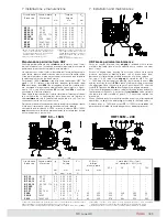
Manutenzione periodica freno HBV
HBV brake periodical maintenance
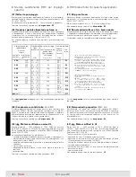
Verificare periodicamente che il
traferro
sia compreso entro i valori
indicati in tabella.
Un valore eccessivo del traferro, derivante dall’usura della guarni-
zione di attrito, rende il freno meno silenzioso e può causare o la
ri duzione fino a zero del momento frenante o problemi di sbloccag-
gio elettrico del freno stesso.
Per registrare il
traferro
,
anche a copriventola montato
, si agisce
sulla vite
48
(HBV) tenendo presente che il passo è: 1 mm per gran-
dezza 63, 1,25 mm per grandezze 71 e 80, 1,5 mm per grandezze
90 ... 112, 1,75 mm per grandezze 132 e 160S.
Dopo ripetute registrazioni del traferro verificare che lo spessore
della guarnizione d’attrito non sia inferiore al valore
minimo
indicato
in tabella; all’occorrenza sostituire il freno.
Verify, at regular intervals, that
air-gap
is included within the values
stated in the table.
Excessive air-gap value, deriving from friction surface wear, could
produce: decrease of braking torque even down to zero, rise of
brake noise level, and even miss of electric release.
Adjust the
air-gap
,
also with mounted fan cover
, acting on screw
48
(HBV) keeping in mind that the pitch is: 1 mm for size 63, 1,25
mm for sizes 71 and 80, 1,5 mm for sizes 90 ... 112, 1,75 mm for
sizes 132 and 160S
After several air-gap adjustments verify that the thickness of the
friction surface is not lower than the
minimum
value stated in the
table; if necessary, replace the brake.
Grand. freno
Grand. motore
Traferro
A
min
Brake size
Motor size
Air-gap
mm
mm
nom. max
1)
V 02
63
0,25 0,45
1
V 03
71
0,25 0,45
1
V 04
80
0,25 0,5
0
1
V 05, G5
90
0,25 0,5
0
1
V 06, G6
100, 112
0,30 0,55
1, 4,5
2)
V 07, G7
132, 160S
0,35 0,6
0
4,5
1) Spessore minimo della guarnizione
d’attrito.
2) Valore per VG6.
1) Minimum thickness of friction surface.
2) Value for VG6.
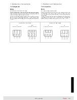
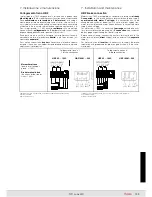
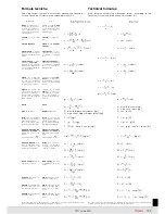
Regolazione del momento frenante (grand
160M)
Il motore viene normalmente fornito con momento frenante tarato a
circa 0,71 volte il momento frenante massimo
M
fmax
(ved. p.to 5.4)
con una tolleranza del
±
18%. Per un corretto impiego del motore
autofrenante occorre regolare il momento frenante in base alle
caratteristiche della macchina accoppiata.
Per impieghi generici è normalmente consigliabile tarare il momento
frenante a circa
due volte
il momento torcente nominale del motore.
In ogni caso il momento frenante deve essere compreso fra i valori
di targa. Se il momento frenante viene tarato a un valore inferiore al
minimo di targa si possono avere frenature incostanti e fortemente
in fluenzate dalla temperatura, dal servizio e dalle condizioni di
usura. Se il momento frenante viene tarato a un valore superiore a
quello di targa si possono avere il mancato o solo parziale sblocco
del freno con conseguenti vibrazioni e surriscaldamento dell’elettro-
magnete ed eventualmente del motore e sollecitazioni meccaniche
tali da compromettere la durata del freno e del motore stesso.
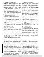
Il momento frenante è direttamente proporzionale alla compressione
delle molle
17
e può essere variato agendo sui dadi autobloccanti
44
avendo cura di comprimere in modo uniforme tutte le molle.
Per la regolazione attenersi alla tabella sottostante dove sono
riportati i valori in mm della lunghezza delle molle in funzione della
percentuale di momento frenante (%
M
fmax
) rispetto al valore mas-
simo
M
fmax
.
Importante
: i valori così ottenuti possono scostarsi leggermente
dal va lore voluto. Pertanto, è consigliabile verificare l’effettivo valore
conseguito tramite una chiave dinamometrica inserita sull’albero
motore lato comando.
Prima della messa in servizio, richiudere il motore con la calotta
co pri freno.
Adjustment of braking torque (size
160M)
Motor is usually supplied with a braking torque set at approx. 0,71
times the maximum braking torque
M
fmax
(see point 5.4) with a tole-
rance of ± 18%. For a correct brake motor application it is necessary
to adjust the braking torque according to specifications of the fitted
machine.
For general applications it is usually advisable to set braking torque
at approx.
twice
the motor nominal torque.
Braking torque must be set within name plate values. If braking
torque is set at a value less than the minimum stated on name
plate, it is possible to have inconstant brakings strongly affected by
temperature, duty cycle and wear conditions. If braking torque is
set at a value higher than the maximum stated on name plate, it is
possible to have missing or partial brake release with consequent
vibrations and overheatings of electromagnet and also of motor and
mechanical stresses affecting brake and motor life.
Braking torque is directly proportional to preload of braking sprin-
gs
17
and can be changed by modifying the self-locking nuts
44
making sure to preload uniformly all springs.
For the adjustment carefully follow table below stating values in mm
of springs length in function of braking torque percentage (%
M
fmax
)
compared to maximum value
M
fmax
.
Important
: values thus obtained can slightly differ from value
desired. Therefore, it is advisable to verify effective value achieved
through a dynamometric key inserted on drive end motor shaft.
Before putting into service, close motor with brake cover.
Summary of Contents for TX11 Series
Page 2: ......
Page 203: ...203 TX11 June 2011...

