194
TX11 June 2011
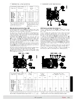
Sonde termiche bimetalliche
Bi-metal thermal probes
Sonde termiche a termistori
Thermistor thermal probes
Scaldiglia anticondensa
Anti-condensation heater
1) Al dispositivo di comando: V
N
= 250 V, I
N
= 1,6A.
2) Termistore conforme a
DIN 44081/44082.
3) Tensione di alimentazio-
ne 230 V ~ ± 5% 50/60 Hz
(15 W per 63, 71, 25 W per
80 ... 112, 40 W per 132 ...
160S, 50 W per 160 ... 180,
65 W per 200 ... 250, 100 W
per 280).
1) To control device: V
N
= 250 V,
I
N
= 1,6A.
2) Thermistor conforms to
DIN 44081/44082.
3) Supply voltage 230 V ~
±
5% 50/60 Hz (15 W, for 63
and 71, 25 W for 80 ... 112,
40 W for 132 ... 160S, 50 W
for 160 ... 180, 65 W for 200
... 250, 100 W for 280).
1)
2)
3)
Cod.
A
Cod.
D
,
F
M, N, P
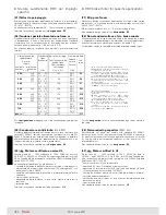
Tensione nominale di alimentazione
Cod. A
3 x
230 V ~ ± 5%, 50/60 Hz
D
3 x Y400 V ~ ± 5%, 50/60 Hz
E
3 x Y460 V ~ ± 5%, 60 Hz
F
3 x Y500 V ~ ± 5%, 50/60 Hz
M
3 x
230 Y 400 V ~ ± 5%, 50 Hz
3 x
277 Y 480 V ~ ± 5%, 60 Hz
N
3 x
255 Y 440 V ~ ± 5%, 60 Hz
P
3 x
220 Y 380 V ~ ± 5%, 60 Hz
Nominal supply voltage
Cod. A
3 x
230 V ~ ± 5%, 50/60 Hz
D
3 x Y400 V ~ ± 5%, 50/60 Hz
E
3 x Y460 V ~ ± 5%, 60 Hz
F
3 x Y500 V ~ ± 5%, 50/60 Hz
M
3 x
230 Y 400 V ~ ± 5%, 50 Hz
3 x
277 Y 480 V ~ ± 5%, 60 Hz
N
3 x
255 Y 440 V ~ ± 5%, 60 Hz
P
3 x
220 Y 380 V ~ ± 5%, 60 Hz
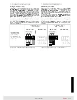
Collegamento di sonde termiche bimetalliche, sonde termiche a
termistori (PTC), scaldiglia anticondensa
I cavetti di collegamento si trovano all’interno della scatola morset-
tiera e sono contrassegnati con la lettera «B» (sonde termiche bime-
talliche), «T» (sonde termiche a termistori PTC) o «S» (scaldiglia
an ti condensa) sui collarini dei capicorda; essi sono collegati a una
morsettiera ausiliaria secondo gli schemi sottostanti.
Le sonde termiche bimetalliche o a termistori necessitano di un
ap posito relé o apparecchiatura di sgancio.
Le scaldiglie anticondensa devono essere alimentate separatamen-
te dal motore e mai durante il funzionamento.
Per il raggiungimento del completo regime termico occorre alimen-
tare le scaldiglie per almeno due ore prima della messa in servizio
del motore.
Connection of bi-metal type thermal probes, thermistor type
thermal probes (PTC), anti-condensation heater
The connection wires are inside the terminal box and are marked by
the letter «B» (bi-metal type thermal probes), «T» (thermistor type
thermal probes PTC) or «S» (anti-condensation heater) on cable ter-
minals; they are connected to an auxiliary terminal block according
to following schemes.
Bi-metal or thermistor type thermal probes need an adequate relay
or a release device.
Anti-condensation heaters must be supplied separately from motor
and never during the operation.
The anti-condensation heater must be supplied for at least two
hours before motor commissioning, in order to achieve a full thermal
steady condition.
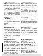
Per individuare il tipo di esecuzione fare riferimento al contrassegno
sui cavi collegati alla morsettiera ausiliaria e al rispettivo codice di
identificazione riportato sulla targa del motore.
Collegamento dell’encoder
Ved. istruzioni specifiche in scatola morsettiera ed avvertenze EMC
al p.to 7.1.
In order to identify the type of design refer to mark on cables con-
nected to auxiliary terminal block and relevant code of identification
as per motor name plate.
Connection of encoder
See specific instructions in terminal box and EMC warning at point
7.1.
7. Installazione e manutenzione
7. Installation and maintenance
Equipaggiamenti ausiliari
(servoventilatore, sonde termiche, scaldiglia anticon-
densa, encoder)
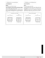
Collegamento del servoventilatore
I cavetti di alimentazione del servoventilatore sono contrassegnati
con la lettera «V» sui collarini dei capicorda e sono collegati ad una
morsettiera ausiliaria secondo gli schemi seguenti, in funzione del
codice di identificazione del servoventilatore.
Codice servoventilatore A: collegamento per alimentazione del ser-
voventilatore monofase (grandezze 63 ... 90).
Codice servoventilatore D, F, M, N, P,: collegamento per alimentazione
del servoventilatore trifase (grandezze 100 ... 280); la fornitura stan-
dard prevede il collegamento a Y con le tensioni sottoindicate; per il
collegamento a
interpellarci. Verificare che il senso di rotazione del
servoventilatore trifase sia quello corretto (il flusso d’aria deve essere
diretto verso il lato comando; ved. freccia riportata su copriventola); in
caso contrario invertire due fasi della linea di alimentazione.
All’installazione, verificare che i dati di alimentazione corrispondano
a quelli del servoventilatore; fare riferimento al codice servoven-
tilatore riportato sulla targa del motore; il funzionamento di motori
con servoventilatore è consentito solo con ventilatore esterno in
funzione; nel caso di funzionamento con marcia e arresto frequenti
alimentare comunque in modo continuo il servoventilatore.
Equipment connections
(independent cooling fan, thermal probes, anti-conden-
sation heater, encoder)
Connection of independent cooling fan
Supply wires of independent cooling fan are marked by the letter
«V» on cable terminals and are connected to auxiliary terminal block
according to following schemes, in function of identification code of
independent cooling fan.
Independent cooling fan code A: connection for single-phase inde-
pendent cooling fan supply (sizes 63 ... 90).
Independent cooling fan code D, F, M, N, P,: connection for three-
phase independent cooling fan supply (sizes 100 ... 280); usual
arrangement is with Y-connection with voltages indicated below;
for
- connection, consult us. Verify that the direction of rotation of
three-phase independent cooling fan is correct (air flow must be
towards drive-end; see arrow on fan cover); on the contrary invert
two phases at the terminals.
During the installation, verify that the supply data correspond to
those of the independent cooling fan; refer to code of independent
cooling fan as per motor name plate; running of motors with inde-
pendent cooling fan is allowed only when external fan is running;
in case of running with frequent starts and stops, it is necessary to
supply the independent cooling fan continuously.
Summary of Contents for TX11 Series
Page 2: ......
Page 203: ...203 TX11 June 2011...


