68
TX11 June 2011
4.4 Caratteristiche freno motore HBZ
Freno elettromagnetico a molle (si ha automaticamente frenatura quan-
do non è alimentato), con bobina toroidale a
corrente continua
, doppia
superficie frenante, momento frenante
proporzionato
al momento
torcente del motore (normalmente
M
f
≈
2
M
N
) e
registrabile a gradini
.
Concepito per la
massima silenziosità
e
progressività
di intervento (sia
all’avviamento che in frenatura grazie alla minore rapidità, tipica del freno
a c.c., dell’àncora freno, più leggera e meno veloce nell’impatto: il motore
parte leggermente frenato quindi con maggiore progressività) accompa-
gnate da
buona rapidità di sblocco e frenatura
; possibilità di accentua-
re la rapidità, sia allo sblocco (con il raddrizzatore rapido) sia alla frenata,
con apertura dell’alimentazione dal lato c.c.; capacità di lavoro elevata.
Ampia disponibilità di esecuzioni speciali
(volano, encoder, servoven-
tilatore, servoventilatore ed encoder, seconda estremità d’albero, ecc.).
Particolarmente idoneo a impieghi nei quali sono richiesti frenature e
avviamenti regolari e silenziosi e, al tempo stesso, frenature con buo na
rapidità e precisione e numero elevato di interventi.
Quando l’elettromagnete non è alimentato, l’àncora freno, spinta dal le
molle, preme il disco freno sullo scudo posteriore generando il mo mento
frenante sul disco freno stesso e conseguentemente sull’albero motore
sul quale è calettato; alimentando il freno l’elettromagnete at trae verso
di sé l’àncora freno, liberando il disco freno e l’albero motore.
Caratteristiche principali:
– tensione di
alimentazione raddrizzatore
(sempre fornito in scatola
morsettiera) alternata monofase:
–
110
÷
480
V c.a.
, (freno 12 … 15) o
200
÷
480
V c.a.
, (freno 06 ... 07)
50
÷
60
Hz
:
raddrizzatore multitensione
(di serie), appositamente
progettato per la gestione di un’
unica bobina freno
con tensione
di alimentazione
sempre coordinata
con la tensione standard del
motore HBZ
(
Δ
230 Y400 V
±
5% 50 Hz
e corrispondentemente
anche
Δ
277 Y480 V
±
5% 60 Hz
);
–
400 V
±
5% 50
o
60 Hz
(grand.
160M per motori avvolti ∆ 400V
50 Hz):
raddrizzatore a semplice semionda
;
– a richiesta altre tensioni, ved. cap. 4.9 (1) e (26);
– alimentazione del raddrizzatore
direttamente da morsettiera
motore
o indifferentemente da linea
separata
;
– momento frenante registrabile cambiando il numero delle molle;
–
classe isolamento F
,
sovratemperatura classe B
;
– disco freno scorrevole sul mozzo trascinatore: con anima d’acciaio e
doppia guarnizione d’attrito a medio coefficiente d’attrito per bassa
usura;
–
àncora freno in due parti
per maggiore rapidità di funzionamento e
silenziosità;
–
guaina antipolvere ed antiacqua
e
V-ring
sia per impedire l’entrata
di inquinamento dall’esterno verso il freno sia per evitare che la polvere
di usura della guarnizione di attrito venga dispersa nell’ambiente;
– a richiesta (di serie per grand.
160M), predisposizione per
rotazione
manuale
per mezzo di chiave maschio esagonale diritta (chiave 5 per
grandezze 63 e 71, 6 per 80 e 90, 8 per 100 e 112, 10 per 132 ...160S,
12 per 160M ... 200) che si impegna sull’albero motore lato opposto
comando (escluse le esecuzioni speciali «Servoventilatore assiale» e
«Servoventilatore assiale ed encoder» cap. 4.7 (17), (18));
– a richiesta (di serie per grand.
160M),
leva di sblocco manuale
con ritorno automatico
e asta della leva asportabile; posizione leva
di sblocco corrispondente alla scatola morsettiera come negli schemi
al p.to 4.8; a richiesta, altre posizioni possibili; interpellarci;
– per altre caratteristiche funzionali ved. tabella seguente.
Per caratteristiche generali motore ved. cap. 4.2.
Per esecuzioni speciali ved. cap. 4.9.
Electromagnetic spring loaded brake (braking occurs automatically when
it is not supplied), with
d.c.
toroidal coil and double braking surface,
braking torque
proportioned
to motor torque (usually
M
f
≈
2
M
N
) and
step adjustable
.
Conceived for
maximum reduced noise level of running
and
pro-
gressivity
of on-off switching (both when starting and when braking
thanks to lower rapidity, typical of d.c. brake, of brake anchor, lighter
and less quick in the impact: motor starts slightly braked and with gre-
ater progressivity)
with increased rapidity in releasing and braking
;
possibility to increase the rapidity, both in releasing (with rapid rectifier)
and braking with supply opening on d.c. side, outstanding work capacity.
Wide range of non-standard designs
(flywheel, encoder, independent
cooling fan, independent cooling fan with encoder, second shaft end,
etc.).
Particularly suitable for applications requiring regular and low-noise star-
ting and braking and, at the same time, braking with good rapidity and
precision and high number of starts.
When electromagnet is not supplied, the brake anchor pushed by
springs presses the brake disk on rear endshield generating the braking
torque on the same brake disk and consequentely on motor shaft it is
keyed onto; by supplying the brake the electromagnet draws the brake
anchor and releases the brake disk and driving shaft.
Main specifications:
– alternate single-phase
supply voltage
of rectifier (always supplied in
terminal box)
–
110
÷
480
V c.a.
, (brake 12 … 15) or
200
÷
480
V c.a.
, (brake 06 ...
07)
50
÷
60 Hz
:
multi-voltage rectifier
(as standard), properly desi-
gned to manage a
unique brake
coil
with supply voltage
always
co-ordinated
with
HBZ motor
standard voltage (
Δ
230 Y400 V
±
5%
50 Hz
and consequently also
Δ
277 Y480 V
±
5% 60 Hz
);
–
400 V
±
5% 50
or
60 Hz
(sizes
160M for ∆ 400V 50 Hz wound
motors):
simple half-wave rectifier
;
– on request toher voltages, see ch. 4.9 (1) and (26);
– rectifier supply
directly from
motor
terminal block
or indifferently
from
separate
line;
– braking torque adjustable by changing number of springs;
–
insulation class F
,
temperature rise class B
;
– brake disk, sliding on moving hub: with single steel coat and double
friction surface with average friction coefficient for low wear;
–
brake anchor in two pieces
for greater rapidity of starting and redu-
ced noise;
–
water-proof and dust-proof gaiter
and
V-ring
both to prevent pol-
luting infiltrations from surroundings towards brake, and to avoid that
wear dust of friction surface will be dispersed in the surroundings;
– on request (as standard for sies
160M), pre-arranged for
manual
rotation
by straight setscrew (wrench 5 for sizes 63 and 71, 6 for 80
and 90, 8 for 100 and 112, 10 for 132 ... 160S, 12 for 160M ... 200) that
can be fitted on non-drive end motor shaft (excluded non-standard
designs «Axial independent cooling fan» and «Axial independent coo-
ling fan and encoder» ch. 4.7 (17), (18));
–
lever for manual release with automatic return
and removable level
rod, on request (as standard for sizes
160M); position of release
lever corresponding to terminal box as in the schemes at point 4.8;
on request, other possible positions; consult us;
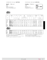
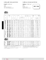
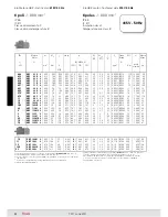
– for other functional specifications see following table.
For main specifications of motor see ch. 4.2.
For non-standard designs see ch. 4.9.
63 ... 160S
160M ... 200
4.4 HBZ motor brake specifications
* A richiesta
* On request
4. Motore autofrenante HBZ per motoriduttori
4. HBZ brake motor for gearmotors
Summary of Contents for TX11 Series
Page 2: ......
Page 203: ...203 TX11 June 2011...

