USER'S AND
MAINTENANCE
MANUAL
Date:
01/31/2020
Code
MAN D185T4F-DB
ENG
Air Compressor : D185T4F-DB
Revision 03
Copyright © 2014, ROTAIR S.P.A. - All rights reserved
.
This manual is intellectual property of ROTAIR S.P.A.
Its full or partial reproduction is forbidden under any form, on any support and by any means, without the
written authorization by ROTAIR S.P.A.
Page
24/59
7
MACHINERY COMPONENTS
This unit D185T4F-DB is a single-phase, silenced oil injection screw
air
compressor. The engine is
an
internal-combustion, fueled by gas
or diesel,
and is connected to the compressor by a flexible coupling.
7.1 Body
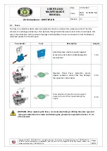
The body is built entirely out of galvanized sheet iron. Panels can easily be removed to allow convenient
access to the main machine parts. The machine is entirely lined with sound absorbent and fire-retardant
material. Special holes have been created in the panels forming the body, complete with baffles, which allow
the cool air necessary for engine and compressor cooling, to be sucked in from one side and the heated air
to be expelled from the other side. These baffles have been carefully designed in terms of size and shape so
as to allow the most efficient internal ventilation of the machine. Therefore, it is advisable to ensure that these
openings are kept free from debris and remain undamaged.
All of the parts of the body have been treated
with a special painting process which guarantees excellent finishing quality
,
together with maximum impact
and rust resistance.
7.2 Engine
The unit is equipped with a diesel engine whose features are described in Section 2.
As related to the user's and maintenance instructions, refer to the manual provided by the
m
anufacturer
and
the enclosed
documentation relevant to this machinery.
7.3 Compressor unit
It is completely manufactured in the ROTAIR factory and consists of a central body cylinder inside
,
which
is
fitted
with
two screw rotors with asymmetric section, a male one with 5 lobes and female one with 6 lobes.
The cylinder is closed at the ends by two head sections which contain the bearings
that
bear the radial and
axial loads created by the air compression. A series of channels inside the cylinder and heads deliver the oil
to the various components. The distribution of the lubricant
serves to lubricate the bearings and maintain a
coating of oil between the rotors and the bearings themselves as well as the internal cylinder walls, thereby
promoting compression resistance. Another important function of the oil injected between the rotors is that of
absorbing the heat generated by the compression
of the air.
The compressed air supplied by this compressor
is free of any pulsations
,
and compression comes about axially.
A "regulator" unit is mounted on the compress
or
unit
to regulate the quantity of air taken in according to
the amount of air consumed. A double-stage filter mounted on the top of this unit guarantees maximum
purity of the suctioned air.
7.4
Oil mist s
eparator tank
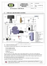
The oil mist separator tank consists of a pressurized container, and, due to its construction features, it is
exempt from the annual I.S.P.E.L. inspection and is supplied with a conformity certificate issued by the
manufacturer. The identification and inspection details are stamped on a plate which is welded to the
machine.
The lid features the following elements: safety valve for overpressure, a thermal switch which intervenes if the
temperature inside the tank exceeds 100°C (212°F), and valves which regulate the maximum and minimum
pressure of the machine.


