background image

USER'S AND 

MAINTENANCE 

MANUAL 

Date: 

01/31/2020 

Code 

MAN  D185T4F-DB 

ENG 

Air Compressor : D185T4F-DB 

Revision  03 

Copyright © 2014, ROTAIR S.P.A. - All rights reserved

.

 This manual is intellectual property of ROTAIR S.P.A. 

Its  full  or  partial  reproduction  is  forbidden  under  any  form,  on  any  support  and  by  any  means,  without  the 

written authorization by  ROTAIR S.P.A. 

Page 

32/59 

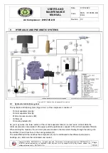
From the compressor (F), the oil

 is

 mixed with the compressed ai

r from the 

check valve (8) 

and 

is sent to the 

separator tank (A), where, through a forced centrifugal circuit, 

the first separation of the 

compressed air 

from 

the 

oil 

occurs. The resulting compressed air leaves the separator tank through the oil mist separator filter (G), 

which will provide a second and last separation of the 

oil

 from the 

compressed air

Even though the separating filter (G) separates the oil from the air, it is worth pointing out that a limited quantity


of oil manages to penetrate inside the 

oil mist separator 

filter and deposits on the lower portion of the filter 

itself.
The oil is sucked into the tubing where a calibrated nozzle (7) and a check-valve (8) will route it to the compressor


(F). The  check  valve  (8)  shall  prevent  the  oil  from  retu

rn

ing  to  the 

oil  mist 

separator  filter  (G)  when  the 

machine  is stopped.  

Attention

The oil filter (C) is provided with a “by-pass” valve which allows the oil to circulate in case it is 

clogged. In such case, the oil shall circulate regularly without being filtered. 

WARNING:  The  filter  therefore  needs  to  be  replaced  at  regular  intervals,  as  specified  in  the


maintenance program.


9.2  Pneumatic system 

The pneumatic system (Figure 8.4-1) includes: 

-

start/work valve (1)

-

suction filter (6)

-

suction adjustment valve (2)

-

compressor (F)

-

separator tank (A)

-

oil mist 

separator filter (G)

-

min. pressure and check valves integrated i

n

 the valve (B2)

-

air valve

 (11)

-

m

ax. pressure valve (4)

The compressor suction air, after passing through the air filter (6), reaches the suction adjuster (2) and then 
the compressor (F), which, after compressing it, directs it together with the injected oil into the separator tank 
(A). Here, the 

oil

 is separated from the 

air

. This process, as indicated above, is made by centrifugal force and 

then by the use of the oil mist separator filter (G).
Once the air is separated from the oil, it is routed to the minimum pressure valve (B2) which opens only when 
the pressure in the tank has reached the established value.  
It is in any case a good practice not to use tools that, with their excessive consumption, may cause the 
lowering of the pressure in the tank under 5-5.2 bar

/

72.5-75psi. Lengthened working conditions below 5 

bar

/

72.5 psi may create insufficient separation of 

the 

oil from the air with subsequent excessive consumption 

of lubricant. Furthermore, the minimum pressure valve (B2) acts as a check valve, thus preventing the return 
of compressed air into the unit from piping or tools connected to the machinery.

WARNING: 

P

ressure tank

Summary of Contents for Dustless Blasting D185T4F-DB

Page 1: ...opyright 2014 ROTAIR S P A All rights reserved This manual is intellectual property of ROTAIR S P A Its full or partial reproduction is forbidden under any form on any support and by any means without...

Page 2: ...means without the written authorization by ROTAIR S P A Page 2 59 Dear customer Thank you for purchasing this ROTAIR Air Compressor which is designed and manufactured in compliance with high standards...

Page 3: ...mendations of the utmost importance concerning the safe appropriate and cost effective operation of the machine Complying with these recommendations helps prevent potentially hazardous situations addi...

Page 4: ...8 1 1 14 Manufacturer 8 1 2 Machinery Identification 8 1 3 General technical standards 9 1 4 General description of the machinery 10 2 Technical specifications of the machinery 11 2 1 General technic...

Page 5: ...f the air compressor 34 10 1 Before starting 34 10 2 Starting 35 10 3 During operation 37 10 4 Stopping the engine 37 10 5 After stopping the engine 37 11 Monitoring and testing of the machine 38 11 1...

Page 6: ...A Page 6 59 13 4 9 Compressor oil filter replacement 52 13 4 10 Replacing compressor oil 53 13 4 11 Checking the oil mist separator 54 13 4 12 Replacing the oil mist separator filter 54 13 4 13 Engine...

Page 7: ...f the machinery Training in basic first aid activities 1 1 2 HAZARD A potential source of injury or damage to health 1 1 3 HAZARDOUS AREA Any area within and or in proximity of machinery where the pre...

Page 8: ...MANUFACTURER Physical or legal person who designed and or developed machinery or partly completed machinery which is subject of this directive and who is liable for the compliance of the machinery or...

Page 9: ...ystems related components for hydraulic and pneumatic transmission Pneumatics UNI EN 349 Safety of machinery Minimum openings to prevent the crushing of parts of the human body D LGS January 27th 2010...

Page 10: ...ers drilling hammers vibrators drilling machines rammers coating machines etc Each of these tools accessories has its own consumption of compressed air expressed in liters per minute l m The optimum c...

Page 11: ...sure 5200 lt min 185 CFM Cooling system Hydraulic oil Hydraulic system capacity 9 lt 2 4 gal Separator tank capacity 20 lt 5 3 gal We recommend ROTAIR COMPRESSOR 46 Copyright 2014 ROTAIR S P A All rig...

Page 12: ...Kohler Lombardini Type KDI 1903 TCR Turbo intercooler Number of cylinders 3 Fuel Diesel Cooling By liquid Power available 42 Kw 57Hp 2600 RPM Maximum revolutions per minute 2600 RPM Minimum revolutio...

Page 13: ...TAIR S P A All rights reserved This manual is intellectual property of ROTAIR S P A Its full or partial reproduction is forbidden under any form on any support and by any means without the written aut...

Page 14: ...to prevent damage WARNING FOR ELECTRICAL HAZARD The pictogram calls attention to specific recommendations in order to prevent damage WARNING FOR CRUSHING OR PERSONAL INJURY HAZARD The pictogram calls...

Page 15: ...ECTION EQUIPMENT OR GUARDS The pictogram instructs that the users SHOULD NOT remove protective equipment such as fixed movable and interlocking guards and SHOULD NOT tamper with photocells or photocel...

Page 16: ...Y REQUIREMENT TO USE THE SUPPORT FOOT PARKING BRAKE AND WHEEL LOCKING WEDGES 3 4 General notices This manual includes the user s and routine maintenance instructions for the machinery Whenever it is n...

Page 17: ...l must be preserved with care in its folder far from sources of humidity heat and sun rays so that it can be consulted at any time by both the personnel appointed to its use and by those who need to p...

Page 18: ...ed air consumption does not exceed 85 of the air generated by the compressor Furthermore it must be taken into consideration that the quantity of compressed air required by the tool shall increase ove...

Page 19: ...ase an educated user will operate the machinery an appropriate distance away from the work area The machinery has been designed and built to work with the hood closed and consequently DO NOT keep it o...

Page 20: ...by third parties if in conflict with the safety regulations and standards of the machine manufacturer Ensure that the activities are performed by purposely appointed personnel only The actions on the...

Page 21: ...for easy access to the lifting hook List of the operations for the safe lifting of the machine 1 Make sure that the lifting device crane hoist etc is of the appropriate payload for the weight of the...

Page 22: ...ations 2 All of the maintenance activities need to be performed after a safe stop of the machine and an interruption of the power supply to the engine 3 If the machinery is stopped during the maintena...

Page 23: ...e to cool down for a few minutes 2 Avoid storing containers with flammable or non flammable liquid inside the toolbox 3 If you use the toolbox to store tools and other objects during the compressor s...

Page 24: ...ded by the manufacturer and the enclosed documentation relevant to this machinery 7 3 Compressor unit It is completely manufactured in the ROTAIR factory and consists of a central body cylinder inside...

Page 25: ...between the engine flywheel and the compressor shaft A large size block joint with rubber pieces inter spaced transmits power in a smooth and silent way without splitting The engine and compressor onc...

Page 26: ...ion is forbidden under any form on any support and by any means without the written authorization by ROTAIR S P A Page 26 59 8 ELECTRICAL EQUIPMENT OF THE MACHINERY WARNING any action on the electrica...

Page 27: ...property of ROTAIR S P A Its full or partial reproduction is forbidden under any form on any support and by any means without the written authorization by ROTAIR S P A Page 27 59 8 2 Operator s panel...

Page 28: ...ustomer service 3 the engine thermostat does not operate correctly replace 4 check for coolant leaks contact ROTAIR customer service 5 air flow to the radiator is obstructed remove the obstruction con...

Page 29: ...ight 2014 ROTAIR S P A All rights reserved This manual is intellectual property of ROTAIR S P A Its full or partial reproduction is forbidden under any form on any support and by any means without the...

Page 30: ...through which the rated current of the circuit travels this wire is the actual fuse with a precise amperage load capability In case of excessive current the filament melts and causes the circuit to op...

Page 31: ...t separator tank A Oil mist separator filter G Minimum pressure valve B2 Oil filter C Oil cooling radiator D As you may notice the lower portion of the oil mist separator tank A is used as an oil tank...

Page 32: ...case it is clogged In such case the oil shall circulate regularly without being filtered WARNING The filter therefore needs to be replaced at regular intervals as specified in the maintenance program...

Page 33: ...ecelerates the engine 5 At the same time the suction adjustment valve 2 proportionally closes as well thus reducing the passage of the air being taken in Consequently with the air valve 11 closed and...

Page 34: ...he battery and that the ground cable is connected to the negative pole of the battery 3 Check the fuel level in the tank USE DIESEL FUEL ONLY 4 Check the level of the engine oil As related to the type...

Page 35: ...3 Figure 10 1 3 Checking the radiator coolant Recommended cooling liquid ROLOIL ROL ICE BLU WARNING The radiator cap Figure 10 1 3 must never be removed when the engine is hot this would cause a sudd...

Page 36: ...sor by pushing the Start button Part 3 Figure 8 1 1 The starter motor is powered by the push button which will start the diesel engine WARNING Release the button at the first sign that the diesel engi...

Page 37: ...ructions to the ventilation system Figure 10 3 1 Exhaust pipe WARNING Areas near the exhaust pipes are very hot and exhaust gases are harmful Avoid coming in close proximity of the exhaust system 10 4...

Page 38: ...isks Presence of hot surfaces at high temperatures 11 1 1 CONTROL SYSTEM OF MAXIMUM ENGINE SPEED The calibration of the maximum speed is set by the manufacturer It should not be changed for any reason...

Page 39: ...zation by ROTAIR S P A Page 39 59 8 Measure with an optical tachometer Letter B in Figure 11 1 2 the RPM of the harmonic balancer focusing the optical beam on the reflective indicator Letter A in Figu...

Page 40: ...e engine is at idle speed 3 Close all air valves Figure 10 2 1 4 Open the hood with the engine running and loosen the 22mm lock nut Letter A in Figure 11 2 1 on the maximum pressure valve 5 To increas...

Page 41: ...rom the value specified in Section 2 2 of this manual proceed as follows 1 Start the machine as described in Section 10 2 Starting 2 Wait for the compressor to reach maximum pressure when the engine i...

Page 42: ...y doing the following 1 Start the machine as described in Section 10 2 Starting 2 With the air valves closed and the engine at idle speed using smooth needle nose pliers pull out on the pin as shown i...

Page 43: ...machine Most maintenance and service will be performed with the machine stopped and the power switched off on the electrical panel The maintenance and service technicians must check that they have rem...

Page 44: ...r fuel leakage Daily Check operation indicator warning lights Daily Check the readability of measuring instruments Daily General cleaning operations Daily Check for obstructions to the ventilation sys...

Page 45: ...and engine silent blocks Every 50 hours Check the torque of all screws and bolts Every 100 hours Check tightness of all pipe tubing connections Every 100 hours Replace compressor air filter After 500...

Page 46: ...ecommend the use of torque wrenches for tightening the screws and bolts on the machine Torques not binding N m Newton meters These pairs are reference values for normal metric threads according to DIN...

Page 47: ...e performed periodically after every 100 hours of work If the machine operates in severe conditions especially very dusty environments it will be necessary to perform these checks on a daily basis COM...

Page 48: ...ls starting with the negative terminal and clean the terminals Checking the clamps Generally the negative and positive poles of the battery are greased eg Pulp Vaseline or similar product to avoid the...

Page 49: ...REPLACEMENT Fuse replacement should be performed when one or both fuses are damaged To replace the fuse proceed as follows 1 Stop the machine 2 Open the hood 3 Open the fuse box 4 Pull the fuse to be...

Page 50: ...that you check the radiator fins periodically and if necessary clean them with compressed air or a jet of water under pressure 13 4 5 PERCENTAGE MIXTURE OF COOLANT To determine the proper amount of an...

Page 51: ...ansparent Z You will notice a certain amount of oil flow from the fitting Z towards the head of the compressor Figure 13 4 4 Nozzle oil recovery 13 4 7 DRAINING THE FUEL TANK The draining of the fuel...

Page 52: ...ctions regarding replacing the diesel pre filter diesel filter engine oil and other specific filters refer to the owner s manual of the engine manufacturer attached to this documentation 13 4 9 COMPRE...

Page 53: ...e compressor oil replacement must be performed taking into consideration the working conditions in which the machine operates standard severe dusty very high temperatures etc The oil change intervals...

Page 54: ...r will need to be replaced To determine the degree of restriction of the oil mist separator filter proceed as follows 1 Install a pressure gauge upstream of the separator and make sure that the engine...

Page 55: ...orbidden under any form on any support and by any means without the written authorization by ROTAIR S P A Page 55 59 13 4 13 ENGINE CONTROL AND MAINTENANCE As for the controls of the engine and replac...

Page 56: ...r and then replace it The temperature light on the control panel should go off when the faulty sensor is disconnected Starter defective injectors failures Seek customer service support from the engine...

Page 57: ...s eventual replacement in Section 13 4 15 The spring in the accelerator piston is broken needs to be adjusted Check the tension of the spring piston accelerator Section 11 1 2 Engine speed is lower th...

Page 58: ...ts of the machine one by one dividing them according to their material composition The various components of the machine have to be disposed of based on the type of waste they contain The following de...

Page 59: ...in the countries of use and installation of the machines 18 3 Temporary storage Hazardous or toxic waste is waste containing or contaminated by substances listed in Directives 75 442 CEE 76 403 CEE an...

Reviews: