7
SAFETY DEVICES
ANTI-SHEARING SAFETY.The lift is provided with a device that stops it automatically for a few seconds at approximately 30 cm from
the floor, when the lift is lowered from this point the device produces a warning acoustical signal.
PHOTOELECTRIC SWITCH (PHOTO CELL). A special device to stop the lift during lowering or lifting operations whenever the
presence of obstructions between the two platforms could cause dangerous situations or a difference of 50 mm. exists between the two
platforms.
SAFETY VALVE FOR AUTOMATIC LOWERING CUT OUT. Normally open two way safety valves. They are able to automatically lock a
single or double-acting cylinder in case a sudden increase in velocity occurs. The valves are located inside the cylnders and prevent the
load from failing down in case of sudden pipe bursting or cutting.
DEAD-MAN CONTROL. The car lift is equipped with a dead-man control. Lowering and lifting operations are stopped immediately by
releasing push button controls.
MECHANICAL SAFETY DEVICES. A metallic device, pneumatically operated.
CHAPTER 4- INSTALLATION
UNPACK THE GOODS AND CHECK FOR POSSIBLE DAMAGE BEFORE INSTALLING THE LIFT.
ONLY SKILLED TECHNICIANS, APPOINTED BY THE MANUFACTURER, OR BY AUTHORIZED DEALERS SHOULD BE
ALLOWED TO INSTALL THE CAR LIFT. SERIOUS DAMAGE TO PEOPLE OR EQUIPMENT CAN BE CAUSED IF THIS RULE IS NOT
FOLLOWED.
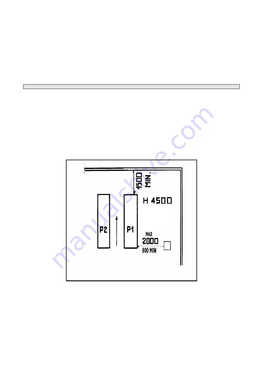
The lift must be installed according to the specified safe distance from walls, columns, other equipments etc. The roof must be a
minimum 4500 mm. in height. The minimum distance from walls must be 1500 mm. take into consideration the necessary space to work
easily. Further space for the control site and for possible walkways in case of emergency is also necessary. The lift can be placed on
any floor, as long as it is perfectly level and sufficiently strong. (250 x cm²).
INSTALLATION PROCEDURE
1. Lift location.
2. Power supply and pneumatic feed availability.
3. Electric connections.
4. Hydraulic connections.
5. Electric network connection.
6. Lift fixing.
7. Initial running.
1) LOCATION OF THE LIFT
Place the automotive lift using a crane truck or any other lifting equipment. Raise the two platforms using a crane, place them at a height
of about 75 cm. (to open) and put a wooden block 10x10 in picture. Move the car lift, sling it as described in diagram and adjust the
distance between the two platforms so that they are exactly parallel. After having set the location of the lift, it may be necessary to level
the unit with metallic shims under the base.
2) POWER SUPPLY AND PNEUMATIC FEED AVAILABILITY CONTROL
The room must be previously arranged for the power supply of the lift. Make sure that supplies are not far from the power unit.
Summary of Contents for GLP99SM
Page 1: ...SCISSOR LIFT FREE WHEELS GEMINI LOW PROFILE OPERATING INSTRUCTIONS GLP99SM GLP99SM P...
Page 9: ...9 WIRING DIAGRAMS...
Page 10: ...10 WIRING DIAGRAM...
Page 11: ...11 WIRING DIAGRAM...
Page 18: ...18...
Page 19: ...19 FIG 3 LEVERS AND PISTON FIG 4 PLATFORM...
Page 20: ...20 FIG 5 CONTROL BOX...
Page 21: ...21 FIG 6 ELECTRIC COMPONENTS FIG 7 SAFETY ELEMENTS FIG 8 RAMPS...


