background image

5

B M W

B M W

B M W

B M W

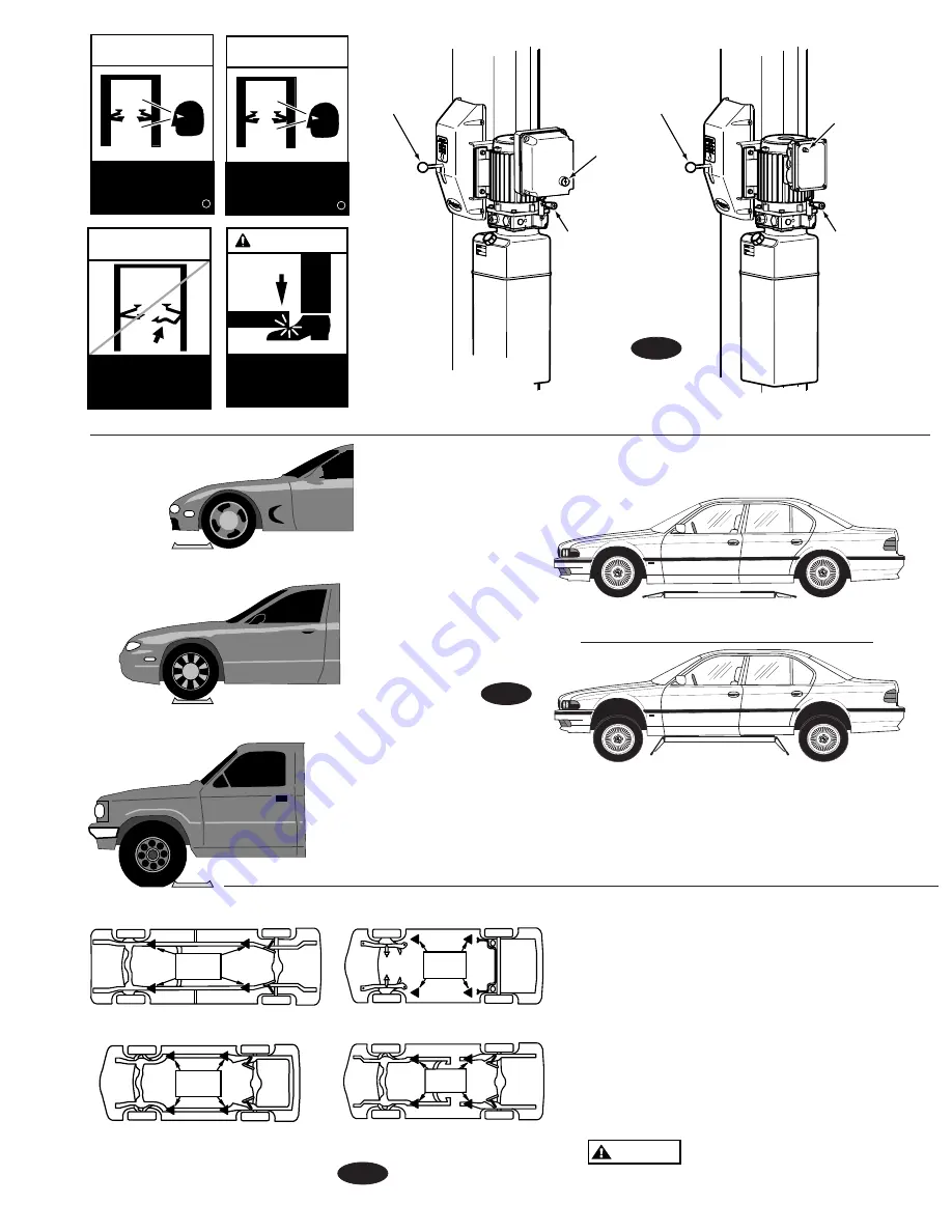
Vehicle Spotting Position

Vehicle Loading Position

FRONT

LIFT

POINTS

FRONT

LIFT

POINTS

FRONT

LIFT

POINTS

FRONT

LIFT

POINTS

Pickup Truck

Perimeter Frame

Unitized Body

Stub Frame

Keep feet 

clear of lift 

while lowering.

©

WARNING

SAFETY

INSTRUCTIONS

Do not operate 

a damaged lift.

©

SAFETY

INSTRUCTIONS

Proper maintenance

and inspection

is necessary

for safe operation.

c

SAFETY

INSTRUCTIONS

Proper maintenance

and inspection

is necessary

for safe operation.

c

Less than 105" 
wheelbase:  
position left front 
wheel on approach 
side of wheel dish.

105"-127" 
wheelbase:  
position left front 
wheel in wheel 
dish.

Larger than 127" 
wheelbase:  
position left front 
wheel just forward 
of wheel dish.

NOTE: Some vehicles may have the manufacturer's 

Service Garage Lift Point locations identified by 

triangle shape marks on it's undercarriage.  Also, 

there may be a label located on the right front door 

lock face showing specific vehicle lift points.  If the 

specific vehicle lift points are not identified, refer to 

the "Typical Lift Points" illustrated herein.  ALWAYS 

follow the operating instructions supplied with the 

lift.

NOTE:  This style lift is not 

recommended for pickup trucks or 

vehicles with truck frames.

Typical Lifting Points

Fig. 5

CAUTION

Fig. 6

Latch 
Release

Raise
Switch

Lowering Valve
Handle

Latch 
Release

Raise
Switch

Lowering Valve
Handle

Fig. 4

Summary of Contents for SPOA7 Series

Page 1: ...All rights reserved CO9020 OM20219 Rev A 5 5 2014 LP20314 Table of Contents Safety Instructions 2 Owner Employer Responsibilities 3 Operating Instructions 4 Maintenance Instructions 6 Trouble Shooting...

Page 2: ...O NOT go under vehicle if locking latches are not engaged Do Not block open or override self closing lift controls they are designed to return to the Off or Neutral position when released Do Not remov...

Page 3: ...Requirements for Operation Inspection and Maintenance and The Employer Shall ensure that lift maintenance personnel are qualified and that they are adequately trained in the maintenance of the lift S...

Page 4: ...ain clear of lift when raising or lowering vehicle CAUTION Always use safety stands when removing or installing heavy components WARNING Do not override self closing lift controls WARNING Remain clear...

Page 5: ...se position left front wheel in wheel dish Larger than 127 wheelbase position left front wheel just forward of wheel dish NOTE Some vehicles may have the manufacturer s Service Garage Lift Point locat...

Page 6: ...locking latch shafts Push latch handle several times for oil to penetrate pivot points Every 3 Months Check anchor bolts for tightness Anchors should be torqued to 65 ft lbs Semi Annually Check fluid...

Page 7: ...ents 2 Break out old concrete and repour new pads for lift per lift installation instructions 1 Remove covers oil latch mechanism Actuate latch release handle several times to allow oil to coat shaft...

Page 8: ...t 2 Unload the subject lift Shut it down and assure the disconnect switch is OFF if one is provided on the lift 3 The authorized lockout person operates the main energy isolation device removing power...

Page 9: ...mber Air Electric Utility Box FA5911 Air Electric Utility Box Without FRL FA5910 Filter Regulator Lubricator FRL FA5166 OPERATING CONDITIONS Lift is not intended for outdoor use and has an operating a...

Page 10: ...10 NOTES...

Page 11: ...11 NOTES...

Page 12: ...otor complies with Underwriters Laboratories Inc standard ANSI UL 201 CSA standard C22 2 No 68 SV0021 B Rev 5 2 14 Rotary Printed in U S A All Rights Reserved Unless otherwise indicated ROTARY DOVER a...

Reviews: