6
7
6
Latch Control Plate
1/4"-20NC x 1-3/4"
HHCS & Nylon Locknut
Clevis Pin &
Retaining Rings
Locking Latch
Air Cylinder
Clevis
Air Cylinder
Bracket
Lowering Switch
Union Tee
To Left Column
Air Cylinder
To Main
Air Supply
1/4" Male
Connector
Fig. 13
(2) 5/16" x 3/8" Lg.
Pan Head Screw &
5/16" Ext. Tooth
Lockwashers
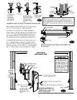
11. Locking Latch & Air Cylinders:
A)
To install cylinder, first slip dampening spacer over
rod with rod in retracted position as shown below, Fig. 12.
B)
Put locknut on threaded shaft and run it down to the
dampening spacer.
C)
Let rod extend and thread locknut down 1-1/2 more
turns.
D)
Screw Bracket Clevis onto shaft, position, and tighten
locknut securely, Fig. 12.
E)
Slide latch control plate into top cylinder Bracket
Clevis.
F)
Insert Pivot Pin through hole in bracket and Latch
Plate. Install one clip ring on each side of Upper Pin.
G)
Extend cylinder where column Pivot Bracket is to be
mounted.
H)
Slide one side of lower Pivot Pin (pre-installed &
fixed in cylinder) into one half of the column Pivot Brack-
et. Install Pivot Bracket into column using (2) 1/4"-20NC
x 3/8" lg. PHMS, Fig. 12.
I)
Install other half of Pivot Bracket the same way.
J)
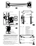
Install air lines from main air supply (with filter) to
lowering valve. Install air line from lowering valve to
union tee then to the right column air cylinder.
K)
Install air line from union tee to left column air cylin-
der. Fig. 14.
L)
Mount lowering valve and bracket to column using
(2) 5/16"-18NC x 3/8" lg. PHMS, Fig. 12.
Note
:
Absence of air filter will void the warranty
on all pneumatic components
Fig. 12
Locking Latch Engagement Test:
A)
Raise carriages past the first latch position and
then lower onto latches.
B)
Check that the latches have fully engaged
when the release switch is not depressed.
C)
Raise carriages fully off latches. Now depress
release switch and check that the latches have
fully disengaged.
D)
Check for air leaks, make necessary adjust-
ments or repairs if required.
E)
Install latch covers with 5/16"-18NC x 3/8"
lg. BHCS, Fig. 13.
Note:
Cut provided tubing with sharp blade to length
as required. Tubing must be cut square with no burrs.
To assemble air line tubing into fitting, use firm, manual
pressure to push tubing into fitting until it
bot-
toms, see below. If removal of the air line tubing from
the fitting is ever required, hold Push Sleeve in (against
fitting) and at the same time, pull out on tubing.
Fig. 14
Fig. 12b
5/16-18NC x 3/8" lg. BHCS
Latch Control
Cover
Air Line
Tubing
Push
Sleeve
* Do Not Route Switch Cord Thru This Hole
Overhead
Assy.
Air line comes out
on the front side of
lift on Left column
This line to
Main Air Supply
APPROACH
Rear View of Lift

