Section 02 717 ENGINE
Subsection 03 (TOP END)
INSPECTION
Refer to table below to find top end engine dimen-
sion specifications. For dimension measurement
procedures, refer to ENGINE MEASUREMENT.
Visually inspect all parts for corrosion damage.
Inspect pistons for damage. Light scratches can
be sanded with a fine sand paper.
NOTE:
When repairing a seized engine, connect-
ing rods should be checked for straightness and
crankshaft for deflection/misalignment.
Inspect plane surfaces for warpage. Small defor-
mation can be corrected by grinding surface with
a fine sand paper. Install sand paper on a surface
plate and rub part against oiled sand paper.
TOLERANCES
ENGINE
MEASUREMENT
NEW PARTS
(min.) (max.)
WEAR
LIMIT
Combustion chamber
volume
31.2 cc
34.0 cc
N.A.
Cylinder taper
N.A.
0.05 mm
(.002 in)
0.1 mm
(.004 in)
Cylinder out of round
N.A.
0.008 mm
(.0003 in)
0.08 mm
(.003 in)
Piston skirt
N.A.
N.A.
0.12 mm
(.005 in)
Piston/cylinder wall
clearance
0.10 mm
(.0039 in)
N.A.
0.20 mm
(.008 in)
Ring/piston groove
clearance
0.025 mm
(.001 in)
0.070 mm
(.0027 in)
0.20 mm
(.008 in)
Ring end gap
0.25 mm
(.010 in)
0.40 mm
(.016 in)
1.0 mm
(.039 in)
N.A.: NOT APPLICABLE
NOTE:
Replacement cylinder sleeves are available
if necessary. Also, oversize pistons of 0.25 mm
(.010 in) and 0.5 mm (.020 in) are available.
ASSEMBLY
Assembly is essentially the reverse of disassem-
bly procedures. However pay particular attention
to the following.
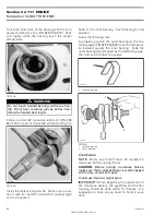
Piston
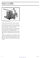
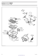
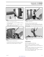
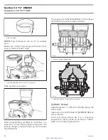
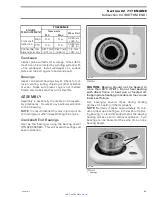
At assembly, place the pistons
no. 8
with the let-
ters
″
AUS
″
(over an arrow on the piston dome) fac-
ing in direction of the exhaust port.
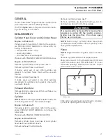
A01C01A
AUS
1
1. Exhaust side
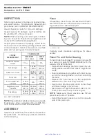
Carefully cover crankcase opening as for disas-
sembly.
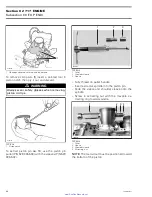
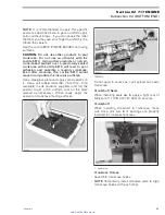
Piston Pin and Roller Bearing
To install roller bearing
no. 11
and piston pin
no. 10
use, piston pin puller (P/N 529 035 503) with the
sleeves (P/N 529 035 542).
– Replacement bearings are held in place by a lo-
cating sleeve outside and 2 plastic cage halves
inside.
– Push needle bearing together with inner halves
out of the locating sleeve into the connecting
rod bore.
– Replace the inner halves by the appropriate
sleeve tool in the connecting rod bore.
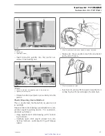
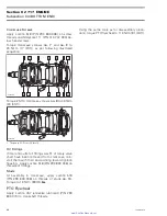
– Insert piston pin into piston until it comes flush
with inward edge of piston hub.
– Warm piston to approximately 50 - 60°C (122 -
140°F) and install it over connecting rod.
NOTE:
Make sure thrust washers
no. 12
are
present each side of needles.
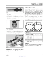
– Install the shoulder sleeve tool on the opposite
side of the piston pin.
30
smr2005-077
www.SeaDooManuals.net

