BRP-Rotax
INSTALLATION MANUAL
INSTALLATION NOTES
General
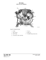
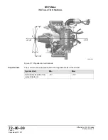
The representation of components in this chapter which are not scope of the delivery is
only symbolic. The design shown in this chapter does not represent a specified execution
but should support the understanding of the system.
The final design, the selection and specification of parts according to the respective appli-
cable regulations, the consideration of the system limitations and interface description as
well as the comprehension of the operating limits in every operational state is in the re-
sponsibility of the aircraft manufacturer.
The aircraft manufacturer has to make sure that the operating limits given in the Operators
Manual can be supervised by the pilot. The execution of the installation must allow the op-
eration of the engine according to the Operators Manual.
ENGINE SUSPENSION
ATTENTION
During engine installation take into account the total engine weight and ensure
careful handling.
The rubber mounts for neutralizing vibrations and other engine suspension components
are not in the scope of delivery. Those components must be designed, selected and
tested on vibration behavior during ground runs and flight testing at specified loads.
ATTENTION
The engine suspension must be designed to prevent excessive engine move-
ment and to minimise noise emission and vibration on the airframe.
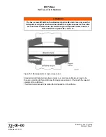
The engine suspension is determined essentially by the aircraft design. Four attachment
points are provided on the engine suspension frame assy.
The engine will be supplied with a well tried and certified suspension frame for attachment
on the fire proof bulk head. The exhaust system and the turbo charger are supported on
this frame, too. The installation into the aircraft is as generally practised by captive rubber
mounts which ensure also to balance out vibrations and sound from engine to aircraft
frame.
Effectivity: 915 i A Series
Edition 0/Rev. 0
Page 11
December 01 2017
Summary of Contents for 915 iS 3 A
Page 165: ......

