BRP-Rotax
INSTALLATION MANUAL
N
NO
OT
TE
E
The switching between several fuel tanks at power loss due to fuel shortage
should be given within a defined period of time and without falling below the mini-
mum performance limit and must be ensured by the aircraft manufacturer. Refer
to the latest requirements such as FAR or EASA.
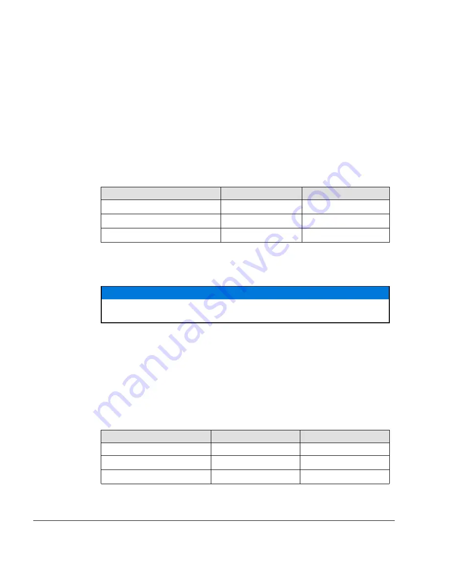
COARSE FILTER
The course filter should be installed at an easy accessible position to allow a periodic
inspection.
Following fuel filter could be used to ensure that the engine is supplied with fuel of an ad-
equate quality:
Interface Parameter
Min.
Max.
Filter mesh size
50 micron (0.0019 in.)
70 micron (0.0028 in.)
Filter surface (total)
64.4 cm² (10 in²)
-
Passing area
18.4 cm² (2.85 in²)
-
The filter should be installed in the supply line between the tank and the fuel pumps and
should be of sufficient capacity to prevent complete blockage between maintenance
intervals.
ATTENTION
An installation without coarse filter may have an significant impact on the proper func-
tionality of this engine.
WATER TRAP, GASCOLATOR
A suitable water trap must be installed. Certification according to the latest regulations,
such as FAR or EASA, must be conducted by the aircraft or fuselage manufacturer.
FINE FILTER
The course filter should be installed at an easy accessible position to allow a periodic in-
spection. To ensure that the engine is supplied with fuel of an adequate quality, a
fine filter with following specifications should be installed between the fuel pumps (module)
and the injection rail (Cylinder 1/3):
Interface Parameter
Min.
Max.
Filter mesh size
8 micron
12 micron
Fuel flow rate
90 l/h (23.8 gal/h)
-
Differential pressure
0.02 bar (0.29 psi)
Page 10
December 01 2017
Effectivity: 915 i A Series
Edition 0/Rev. 0
Summary of Contents for 915 iS 3 A
Page 165: ......

