11
EN
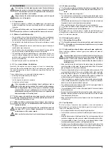
4.7. Concluding mechanical installation instructions
After the first start-up the correct alignment is to be checked while the
motor is as warm as it usually is while operating..
• All screws, nuts and other clamped or bolted connections must be correctly
assembled and fastened.
• The cooling air must be able to circulate without a problem.
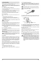
The engines are equipped with a mechanical, adjustable speed regu-
lator. Make sure the injection pipe cannot vibrate with the engine at
any time, particularly when using the device at different speeds. This
could severely damage the injection pipes already after a short period
of time. If necessary support the injection pipes at appropriate spots..
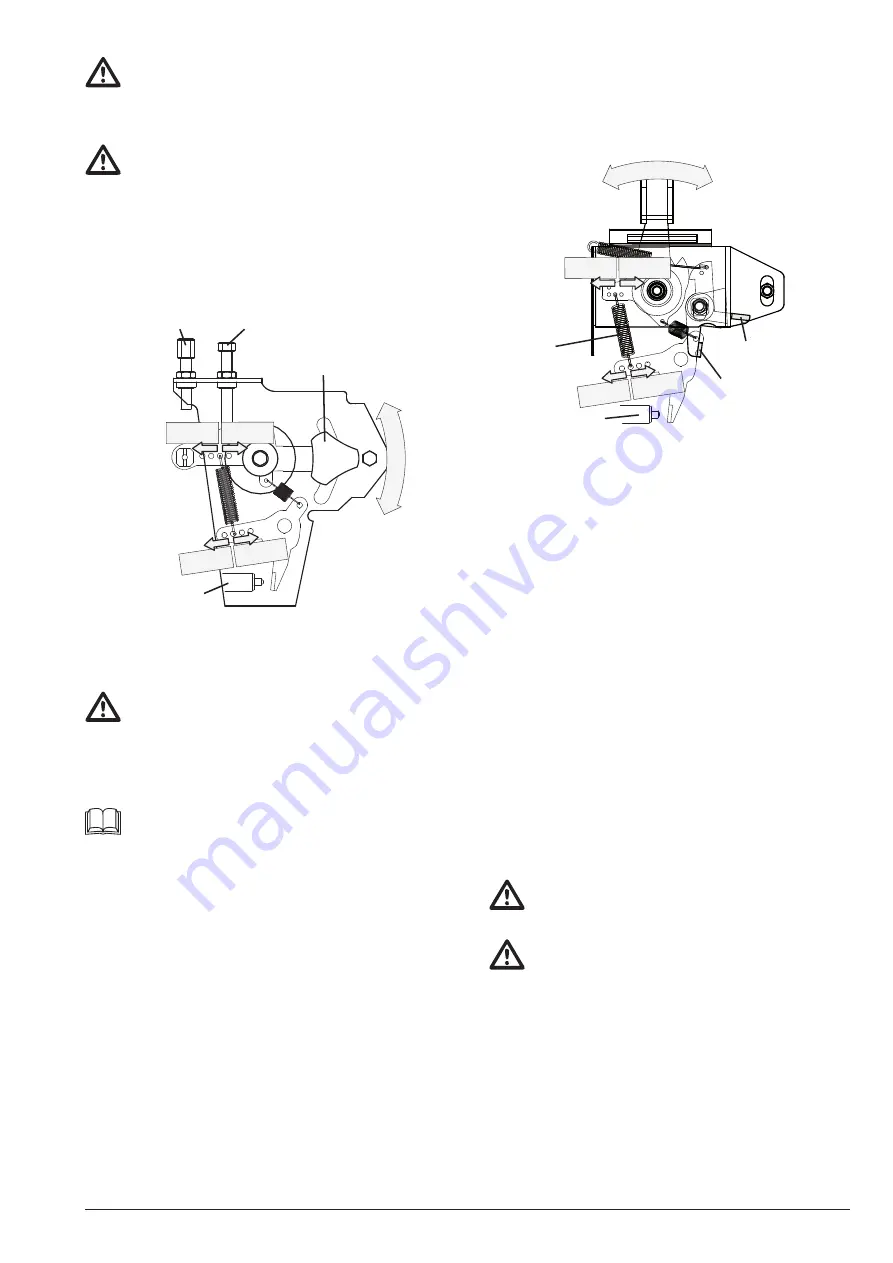
4.8. Speed controller
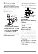
4.8.1. Type “A” – for variable speed
At delivery the engine is set up as follows:
➽
Maximal speed: 3.000 min
-1
➽
Idle speed: 1.300 min
-1
less
oscillate
faster
regulation
higher
speed
lower
speed
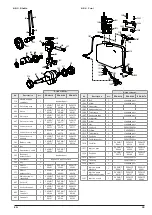
for wire rope
Adjusting screw max. speed
Adjusting screw
max. Injection qty.
Speed adjusting knob
Fasten to hold speed
Idle
Full speed
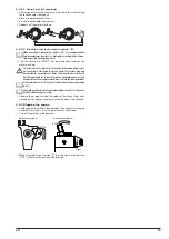
• If necessary attach a appropriate wire rope for speed regulation. There is a
clamp located at the left end of the governor. Here the rope should be attached.
• If an outher maximum speed than 3.000 min-1 is necessary in your applica-
tion, you can adjust the regulation-spring in different positions. Highest allo-
wed speed is 3.700 min
-1
If you change the set-up for the maximum speed, you also have to
readjust the adjusting screw for the maximum injection quantity.
Open the check-nut and adjust the screw as follows:
Load the engine with the nominal load according to the perfor-
mance curve and adjust the screw so that the engine achieves a
Bosch count below 4. Make sure to refasten the check-nut after
the adjustments.
If the engine is used above 1.000m sea level, readjustments of the
maximum injection quantity are also necessary.
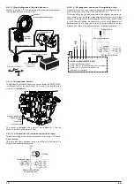
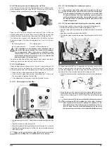
4.8.2. Type “C” – for constant speed
This speed controller is made for fixed speed and is usually used
as a speed controller for generators. At delivery the engine is set up
as follows:
➽
Rated speed: 3.000 min
-1
If you want to change the engine speed, the regulating-spring must
be exchanged.
wire rope slot for
cut-off solenoid
Regulating
spring
Adjusting screw
max. Injection quantity
Bring lever in right position
„click“
cut-off lever
press to stop engine
Engine off
Rated speed
less
oscillate
faster
regulation
higher
speed
lower
speed
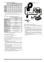
4.9. Electrical installation
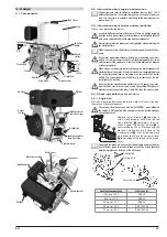
Depending on the version the engine is equipped with following
electrical components:
➽
Version "H":
No electrical components
➽
Version "E":
Dynamo, Battery loading regulator and electric starter
➽
Special components (not included, additionally available):
- Starting battery
- Key box
- Oil pressure sensor
- Injection pump with mounted 12V magnetic valve
4.9.1. Electrical connection (chords)
Only use stranded wire cable as a connection.
B) as well as battery(-) chords are to be held as short as
because the current of the starter is very high.
Note that the motor and add-on-parts get hot when used. Always
protect the cable from touching hot parts by using a protective hose.
Caused by motor vibration during operation all screw connections
must be secured with spring washers or lock-nuts.
4.9.2. Starter battery
A starter battery and a battery cable are not included in the delivery,
they can however be ordered separately as add-ons. Make note of
following points:
Lead acid batteries contain sulfuric acid. If there are liquids
escaping from the battery, do not touch or swallow them.
Carefully dilate the acid with water and neutralize it with soda
(sodium carbonate).
Always wear protective gloves and safety goggles when wor-
king with the starter battery.
• You can find the necessary capacities in the chart in chapter 3.1.
The usage of valve-regulated (maintenance free) batteries is re-
commended..
• Always connect the plus(+) pole first, then the minus(-) pole. Fas-
ten the connections properly.


