background image

9

Mounting the Keypads

Once all of the keypads are connected, pro-

grammed, and tested, finish the installation by 

installing them into electrical boxes. 

NOTE

Purchase decorative switchplate covers to 

match those used in the room for light switches. 

The  RKB-200  is  not  supplied  with  decorative 

switch plate covers because there is no way to 

know which style or color will match in custom 

installations. 

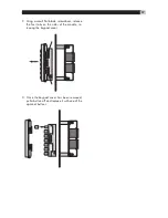
The exact installation steps may vary depending 

on the style of switch plate covers you purchase. 

However, here is a typical installation method us-

ing Decora

® 

style covers:

1.  Remove the mounting bracket from the back 

of the decorative cover.

2.  Place the mounting bracket over the electrical 

box.

3.  Place the keypad through the mounting bracket 

and into the electrical box.

4.  Place two  screws through the mounting tabs on 

the keypad and through the mounting bracket 

to secure the keypad. Do not overtighten.

5.  Place the decorative cover over the keypad 

and press in at the top and bottom until se-

cure. There is a small slot in one edge of the 

decorative cover. Orient the cover so this slot 

is facing down.

NOTE

Do not mount the keypads until all program-

ming steps are complete and the system has been 

tested. Access to DIP switches at the back of the 

keypads is necessary during programming.

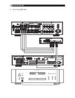
Connecting the RHB-200  

to a Rotel Receiver


See Figure 4

The RHB-200 connecting hub sends command 

codes to a Rotel multi-zone receiver using infra-

red commands. The connections are made using 

two-conductor cables with 3.5mm mono mini 

plugs on both ends. One cable is needed for 

each zone with a keypad, up to a max of four. 

A Rotel RX-1052 multi-zone receiver is shown in 

the example:
1.  Plug one end of the first cable into the ZONE 1 

IR OUT connector on back of the RHB-200.

2.  Plug the other end of the cable into the zone 

1 IR input on the receiver, labeled EXT REM 

IR IN on the Rotel RX-1052.

3.  Repeat for any additional zones, matching 

the ZONE 2 IR OUT on the RHB-200 to the 

ZONE 2 IR IN on the receiver, etc.

Connecting the RHB-200  

to Source Components


See Figure 4

The RHB-200 connecting hub sends command 

codes to source components (such as CD play-

ers) using infrared commands. With most Rotel 

source components, connections are made us-

ing two-conductor cables with 3.5mm mono mini 

plugs on both ends. One cable is needed for each 

source component. 
1.  Plug one end of the cable for the first Rotel 

source component into any of the COMMON 

IR OUT connectors on back of the RHB-200.

2.  Plug the other end of the cable into the EXT 

REM IN IR input on first source component.

3.  Repeat for any source components, using any 

available COMMON IR OUT connectors on 

the RHB-200.

NOTE

If your source component does not have 

an input for a hard-wired IR cable, you can use 

an industry standard IR emitter placed in front of 

the source component’s infrared remote sensor. 

Connect the other end of cable to a COMMON 

IR  OUT  connector  on  the  RHB-200.  This  type 

of source component is shown at the bottom of 

Figure 4.

AC Power connection


Once all of the keypad and IR connections are 

complete, supply power to the RHB-200. 
1.  Plug the connector from the supplied AC 

adaptor into the +12V input on the back of 

the RHB-200. 

2.  Plug the AC adaptor into an AC power wall 

outlet.

Summary of Contents for RHB-200

Page 1: ...RHB 200 Keypad Connecting Hub TUN CD MUTE MP3 OFF AV V V RKP 200 Learning Keypad...

Page 2: ...2 RKP 200 RHB 200 1 RKP 200 Keypad 2 RHB 200 Connecting Hub TUN CD MUTE MP3 OFF AV V V ZONE OUT ZONE IN DC 12V CLONE IN ZONE1 IN ZONE3 IN ZONE4 IN ZONE2 IN IR OUT ZONE3 ZONE4 ZONE1 COMMON IR OUT ZONE2...

Page 3: ...IR OUT ZONE2 TUN CD MUTE MP3 OFF AV V V ZONE OUT ZONE IN TUN CD MUTE MP3 OFF AV V V ZONE OUT ZONE IN TUN CD MUTE MP3 OFF AV V V ZONE OUT ZONE IN TUN CD MUTE MP3 OFF AV V V ZONE OUT ZONE IN TUN CD MUTE...

Page 4: ...UIDE TUNE PRESET FM MONO BAND CTR SUB SUR SEARCH SEARCH OSD ON OFF SMT MUTE CH VOL POWER SMART MEM AUD CD TUN TAPE EXT V1 V2 V3 V4 V5 DEVICE INPUT RR 1060 DC 12V CLONE IN ZONE1 IN ZONE3 IN ZONE4 IN ZO...

Page 5: ...MP3 OFF AV V V ZONE OUT ZONE IN TUN CD MUTE MP3 OFF AV V V ZONE OUT ZONE IN TUN CD MUTE MP3 OFF AV V V ZONE OUT ZONE IN TUN CD MUTE MP3 OFF AV V V ZONE OUT ZONE IN TUN CD MUTE MP3 OFF AV V V ZONE OUT...

Page 6: ...Connecting Master Keypads 8 Connecting a Second Keypad 8 Mounting the Keypads 9 Connecting the RHB 200 to a Rotel Receiver 9 Connecting the RHB 200 to Source Components 9 AC Power connection 9 Operat...

Page 7: ...keypad are per manently con gured as command buttons Pressing a command button sends an IR signal to operate the selected component Multi function Buttons These two buttons are factory programmed as...

Page 8: ...e has different color codes make sure to wire every modular plug in the same order 1 2 3 4 5 6 7 8 GREEN STRIPE GREEN SOLID ORANGE STRIPE BLUE SOLID BLUE STRIPE ORANGE SOLID BROWN STRIPE BROWN SOLID T...

Page 9: ...o mini plugs on both ends One cable is needed for each zone with a keypad up to a max of four A Rotel RX 1052 multi zone receiver is shown in the example 1 Plug one end of the rst cable into the ZONE...

Page 10: ...t the CD player A SMART sequence automatically starts disc playback The following commands are available Select CD input and begin play Random Play Select Disc changers only Track Backward Track Forwa...

Page 11: ...keypads With the default factory con guration the keypads are ready to use in a system with Rotel compo nents as described in the Operating the Keypads section of the manual However the keypads can be...

Page 12: ...e buttons cannot store normal learned commands however they can store a SMART sequence of normal commands that is sent when the device button is pressed The RKP 200 provides the option of designating...

Page 13: ...the ON position these buttons cannot be used to learn commands However they can be used as device buttons with commands learned on other buttons just like the four standard device buttons In addition...

Page 14: ...ttons can be used to store an invisible layer command without overwriting the standard commands stored for each button With an invisible layer for each of the four devic es a total of 56 invisible lay...

Page 15: ...d For ex ample the device button is programmed to switch the Rotel receiver to the CD input and be gin disc play You can store a new SMART sequence for any device button using the following procedure...

Page 16: ...by connecting it to the AC power source The four Zone LEDs on the front of the RHB 200 ash green once The LED on the keypad being cloned ashes once 4 Press the large CLONE button on the front panel of...

Page 17: ...small at blade screwdriver release the four tabs on the sides of the module re leasing the keypad cover 3 Once the keypad cover has been removed pull a button off and replace it with one of the optio...

Page 18: ...Street North Reading MA 01864 2699 USA Phone 1 978 664 3820 Fax 1 978 664 4109 Rotel Europe Dale Road Worthing West Sussex BN11 2BH England Phone 44 0 1903 221600 Fax 44 0 1903 221525 Rotel Deutschla...

Reviews: