2
RLC-1080
Power Conditioner
Place the unit on a fixed, level surface strong enough to support its weight.
Do not place it on a moveable cart that could tip over.
Important Safety Information
WARNING: There are no user serviceable parts inside. Refer all servicing
to qualified service personnel.
WARNING: To reduce the risk of fire or electric shock, be sure that the
apparatus shall not be exposed to dripping or splashing and that no
objects filled with liquids, such as vases, shall be placed on the apparatus.
Do not use this product in an environment where the relative humidity
may exceed 95% (non-condensing).
Do not allow foreign objects to get into the enclosure. If the unit is exposed
to moisture, or a foreign object gets into the enclosure, immediately
disconnect the power cord from the wall. Take the unit to a qualified
service person for inspection and necessary repairs.
Read all the instructions before connecting or operating the component. Keep this manual
so you can refer to these safety instructions.
Heed all warnings and safety information in these instructions and on the product itself.
Follow all operating instructions.
Unplug this device from the wall outlet before cleaning. Clean the enclosure only with a
dry cloth or a vacuum cleaner.
Note:
A product that is meant for uninterrupted service
and for some specific reason, such as the possibility of the loss of an authorization code
for a cable TV converter, is not intended to be unplugged by the user for cleaning or any
other purpose, may exclude the reference to unplugging this device.
You must allow 10 cm or 4 inches of unobstructed clearance around
the unit.
Do not place the unit on a bed, sofa, rug, or similar surface that could block
the ventilation slots. If the component is placed in a bookcase or cabinet, there must be
ventilation of the cabinet to allow proper cooling.
Keep the component away from radiators, heat registers, stoves, or any other appliance
that produces heat.
The unit must be connected to a power supply only of the type and voltage specified
on the rear panel of the unit. Do not use a plug adapter which defeats the ground pin
of the AC plug.
Connect the component to the power outlet only with the supplied power supply cable
or an exact equivalent. Do not modify the supplied cable in any way. Do not attempt to
defeat grounding and/or polarization provisions. Do not use extension cords.
Do not route the power cord where it will be crushed, pinched, bent at severe angles,
exposed to heat, or damaged in any way. Pay particular attention to the power cord
at the plug and where it exits the back of the unit. After connecting other devices to this
device, do not push the rear of the device up against any surface (wall or shelving unit),
as this may create an undesired bend in the power cords which may break the wire
strands of the cord.
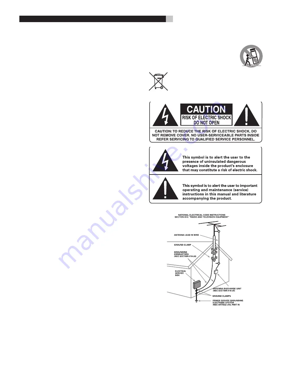
Although this device provides protection against electrical surges, when connecting an
outside antenna or cable system to devices connected to this device, ensure the antenna
or cable system is grounded so as to provide additional protection against voltage
surges and static charges in accordance with Section 810 of the National Electric Code,
ANSI/NFPA No.70 (see illustration).
This device provides a grounding lug at the rear panel for grounding the device to an
external Transient Voltage Surge Suppression (TVSS) device. Ensure this connection is
made in accordance with the instructions provided by the TVSS device.
This device employs Metal Oxide Varisters (MOVs), and other circuitry to protect against
lightning and other sources of voltage surges and sags. It is not necessary to turn this
device or the devices connected to this device, off during a lighting storm.
Do not locate outside antenna systems near overhead power lines, or other electric light
or power circuits, or where it may fall or otherwise come in contact with these power
sources. Do not allow the ladder being used, or the antenna itself to come into contact
with these power sources, as such contact may be fatal.
Do not overload the wall outlet where this device is being connected. Do not overload
this device. Ensure the total load to this device does not exceed that which is listed in the
Specifications section of this manual.
Inspect the line cords. telephone/data cords, or DSS/Cable TV coaxial cables connected
to this device to ensure they remain fully pushed in or attached, and that they are not
frayed or otherwise damaged.
Immediately stop using the component and have it inspected and/or serviced by a
qualified service agency if:
• The power supply cord or plug has been damaged.
• Objects have fallen or liquid has been spilled into the unit.
• The unit has been exposed to rain.
• The unit shows signs of improper operation
• The unit has been dropped or damaged in any way
Federal Communications Commission (FCC) Compliance Information
This device complies with Part 68 and Part 15 of the FCC rules. Operation is subject to
the following two conditions: (1) This device must not cause harmful interference, and (2)
This device must accept any interference received, including interference that may cause
undesired operation. As required, the bottom of this equipment contains, among other
information, the Registration Number and Ringer Equivalence Number (REN) for this
equipment. If requested, this information must be provided to the telephone company.
Rotel products are designed to comply with international directives
on the Restriction of Hazardous Substances (RoHS) in electrical
and electronic equipment and the disposal of Waste Electrical and
Electronic Equipment (WEEE). The crossed wheelie bin symbol indicates
compliance and that the products must be appropriately recycled or
processed in accordance with these directives.


