20
FA ROTEX A1 BGe - 02/2014
4
x
Set-up and installation
4.8.4 Connect the additional electrical components
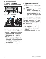
When using a hot water storage tank you must connect a 3-way
diverter valve (a) or a storage tank charging pump (b) to the
switching field board. For this:
a) connect the connection cable of the 3-way diverter valve,
included in the scope of supply of the connecting kit A1
(
VSA1,
15 48 22
) or
b) the adapter cable for the connection of a storage tank charg-
ing pump (
E 1500430
)
the PCB plug
J2
(see fig. 4-13).
Additional optional regulating system components (room con-
trollers, mixer modules etc.) are connected to the switching field
via the PCB plug
J13
.
Additional switching contacts can be connected to the PCB plug
J8
for external boiler control.
4.9 Connect the gas line, check the burner
setting for gas type
4.9.1 Important instructions for gas connection
Gas connection
– Carry out gas connection conforming to the technical rules for
gas installation as well as the relevant specifications of the
country of destination and the gas supply company.
– A thermally triggered blocking device (TAE) and a gas flow
monitor (GSW) with a DVGW inspection symbol must be fit-
ted. The TAE must comply with the test basis of DVGW-
VP 301. The dimensions of the GSW must comply with the
maximum adjustable rated load of the device.
Gas type
– The gas burner has been factory-set for the gas type "natural
gas".
– Observe permitted gas inlet pressure (rest pressure)
(see tab. 12-3).
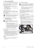
4.9.2 Connecting the gas line
Ɣ
Position the gas intake in such a way that the ROTEX A1 can
be opened without tension or restriction.
Ɣ
Connect the factory-mounted gas connection corrugated
hose (fig. 4-10, Item 3) (pipe thread EN 2999 Rp ½") to the
gas line without tension.
4.9.3 Checking burner pre-setting
Ɣ
Compare the available gas type with the set gas type (sticker
on burner housing).
The two gas types must match. If the burner is not labelled for
the available gas type, convert the burner to the new gas type
and label it (see chapter 7.3 "Burner setting").
Ɣ
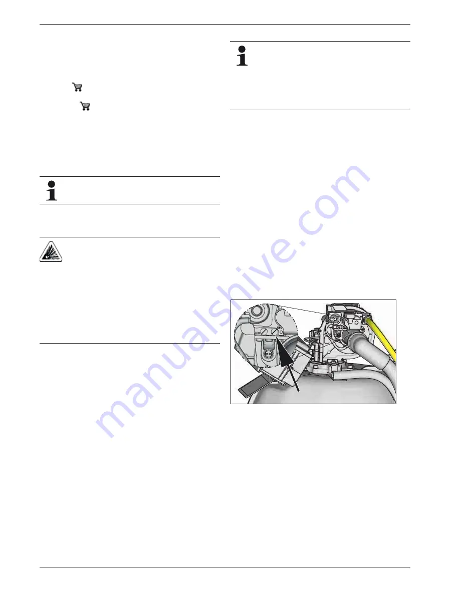
Check the gas inlet pressure.
– If the gas inlet pressure is not within the permissible range
(see tab. 12-3), inform the responsible gas supply com-
pany.
– For liquid gas: Check the pressure reducer or adjust the
burner to the permissible gas inlet pressure
(see chapter 7 "Gas burner"). This adaptation must be
appropriately labelled with a suitable burner settings
sticker and an entry on the settings type plate (fig. 3-1,
item 23).
Additional information and a detailed description can be
found in the documentation "ROTEX Regulator RoCon
BF". It is included in the A1 scope of supply.
DANGER OF EXPLOSION!
Escaping gas is a direct threat to human health and
safety. Even a few sparks can cause very serious ex-
plosions.
Ɣ
Before working on gas carrying parts, always close
the main domestic gas stop valve.
Ɣ
If you can smell gas, ventilate the room thoroughly.
Prevent generating sparks or flames (e.g. from a
naked flame, an electrical switch or mobile phone).
Ɣ
Only heating specialists authorised and trained by
the gas or power supply company should be
allowed to work on gas-conducting parts.
The gas connection corrugated hose is dimensioned in
such a way that the ROTEX A1 can be opened up-
wards. The burner can thus be removed for mainte-
nance without having to disconnect it from the gas con-
nection.
The standard corrugated gas connection hose can
cause a pressure drop of up to 5 mbar. This will not
hinder operation of the ROTEX A1.
Fig. 4-14 Check the gas inlet pressure


