6
x
Control unit
FA ROTEX A1 BGe - 02/2014
25
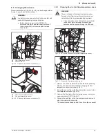
6.2 Replacing the operating section RoCon B1
Removing the operating section
Ɣ
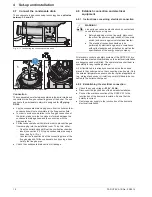
Release the lugs on both sides of the operating section by
sliding in a small flat bladed screwdriver in (fig. 6-2, item 1)
and pull the operating section out to the front.
Ɣ
Unplug the communication cable on the back of the operating
section for complete removal.
Fitting the operating section
Ɣ
Plug in the communication cable on the back of the operating
section.
Ɣ
Slide the operating section into the switching panel cut-out
until the lugs click in place again.
6.3 Changing the boiler control panel
Removal (observe sequence)
The position and arrangement of the components described
below is shown in fig. 6-16 on page 30.
1. Remove the sound insulation hood (see chapter 9.2.1).
2. Remove boiler cladding (see chapter 9.2.1).
3. Remove both top heat insulation shells (see chapter 9.2.1).
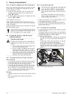
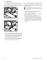
4. Unscrew the switching panel cover and remove (fig. 6-3).
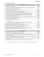
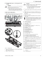
5. Pull out all plugs from the switchboard PCB (fig. 6-4).
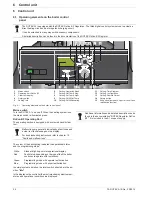
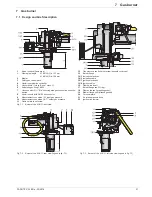
6. Pull out the sensor and the connection cables from the cable
ducts of the control panel (fig. 6-5).
WARNING!
Live parts can cause an electric shock on contact and
cause life-threatening burns and injuries.
Ɣ
Before beginning work on live parts, disconnect
them from the power supply (switch of fuse, main
switch) and secure against unintentional restart.
A
Front view
B
Rear view
1
Operating section RoCon B1
2
Plug connection for commu-
nication cable
3
Communication cable
Fig. 6-2
Removing/fitting the operating section
WARNING!
Live parts can cause an electric shock on contact and
cause life-threatening burns and injuries.
Ɣ
Before beginning work on live parts, disconnect
them from the power supply (switch of fuse, main
switch) and secure against unintentional restart.
Fig. 6-3
Unscrew control panel cover
Fig. 6-4
Pull off the coded connector
Fig. 6-5
Pull out the cable


