48
FA ROTEX A1 BGe - 02/2014
9
x
Service and maintenance
Ɣ
Only on A1 BG 40(F)-e:
Ɣ
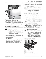
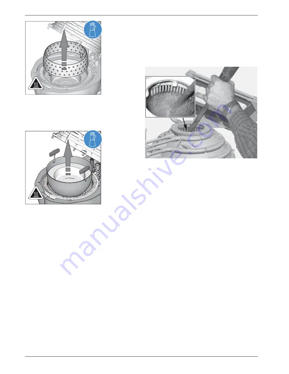
Remove the cylindrical burner chamber.
Ɣ
Remove the lower combustion chamber inset using the
combustion chamber wrench (fig. 9-14).
Cleaning the combustion chamber
Requirement:
The gap between the bottom combustion chamber half and the
sound deadening shell in the joint area is covered to prevent res-
idues from the upper combustion chamber half from falling into
the gap.
Special tool:
Cleaning brush and scraper fixed on the inside of
the boiler panels (included in the supply).
Remove dry residue (mostly in the upper combustion chamber
half):
Ɣ
Loosen the dirt and soot on the combustion chamber ribs by
using the cleaning brush and cleaning scraper.
Ɣ
Suction off the loosened dirt and soot by using a vacuum
cleaner.
Hard residues may arise in the transition region between dry and
water combustion chamber surfaces (usually in the lower half
shell of the boiler). These can only be removed by wet cleaning.
For this:
Ɣ
Loosen the dirt and soot under running water by using the
cleaning brush and cleaning scraper.
Ɣ
Rinse off loosened dirt with clean water into the drain.
Alternatively
, any residue can be removed with a high-pressure
cleaner.
For this:
Ɣ
Close combustion chamber without combustion chamber
insert.
Ɣ
Unscrew burner and burner flange (see chapter 7.4
"Removing/fitting the burner").
Ɣ
Clean combustion chamber through burner flange opening
with high pressure cleaner (fig. 9-15).
Closing the combustion chamber
The combustion chamber is closed again in reverse order to
"Opening the combustion chamber".
The following must be observed:
– Replace the combustion chamber inserts completely if they
were removed for cleaning of the combustion chamber.
Only on A1 BG 40(F)-e:
– There must be no gap between the cylindrical and the lower
combustion chamber insert.
– When folding down the upper combustion chamber half you
must make sure that the upper (perforated) combustion
chamber ring does not tilt over.
– When
tightening
the four
allen bolts
,
start with the two
front bolts
.
Make sure that the upper combustion chamber does not tip
over and that it forms a tight seal.
Fig. 9-13 Lift out the top burner chamber insert
(shown A1 BG 25-e)
Fig. 9-14 Lift out the bottom burner chamber insert
(shown A1 BG 25-e)
Fig. 9-15 Clean combustion chamber with high pressure cleaner


