18
FA ROTEX Solaris DrainBack - 09/2016
4
x
Installation
4.3
Laying the connecting pipe
●
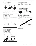
Lay and affix prefabricated connection pipes (inflow and
return flow) with integrated sensor cable (see chap. 3)
between the planned installation location and the solar panel
array in the inner roof and the site of the hot water storage
tank with control system and RPS4 pump unit.
– Make sure there is adequate length for connection to the
hot water storage tank and the flat solar panels.
– Ensure a constant gradient of the connecting pipes (min.
2 %).
– The maximum permissible overall pipe length must not be
exceeded (see tab. 4-2).
If the CON 15 or CON 20 connecting lines do not suffice,
ROTEX recommends using the CON X 25, CON X 50,
CON X 100 or CON XV 80 extension pipes.
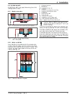
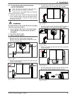
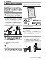
– The inflow connecting pipe (VA15 Solar) must be con-
nected to the top and the return flow connecting pipe
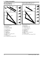
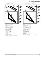
(VA18 Solar) to the bottom of the solar panel (see fig. 4-1
to fig. 4-3 and fig. 4-8).
Tab. 4-2 Maximum lengths of the ROTEX connecting pipes
Additional notes about connecting pipes
If on-site conditions make it impossible or very difficult to install
the connecting pipes in the manner described above, slight devi-
ations from the specified installation are permitted. Hereby, the
inflow pipe may not be larger than 18 x 1 mm.
●
If vertical copper pipes are already installed in the house, they
can be used if a continuous connection pipe gradient can be
guaranteed.
●
If a uniform gradient from the second roof penetration to all
pipe sections can not be guaranteed when the solar panels
are connected at opposite ends, then for roof penetration
purposes, the inflow pipe can be connected to the top of (e.g.
through a ventilating tile), if:
– the highest point if the inflow pipe is not more than 12 m
above the storage tank mounting floor level.
– the internal diameter of the inflow pipe is not more than
16 mm.
– a continuous rise of the inflow pipe to the highest point, as
well as a continuous gradient to the warm water storage
cylinder is ensured.
●
For pipe runs in which only a limited gradient can be
achieved, copper pipe should be used on site. This avoids the
need for a rigid supporting structure, and prevents the
formation of water pockets due to expansion of the plastic
pipes.
Notes on the roof penetration box of the connecting
pipe
Carry out the following steps:
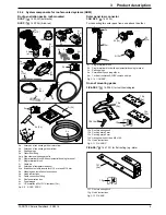
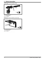
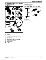
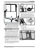
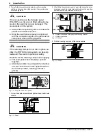
1. Make the roof penetration points as close as possible under
the panel connecting points. Make sure that effective sealing
of the outer roof area can be ensured. Special roof penetra-
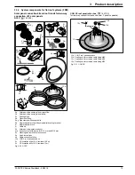
tions for the roof-mounted and the flat roof mounting are avail-
able as system components (see chap. 3.3).
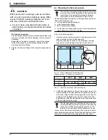
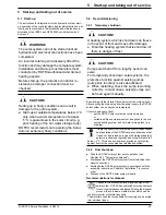
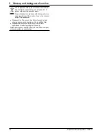
CAUTION!
Siphon action may never be allowed to occur
anywhere in the pipe run between the storage
tank and the flat solar panel. This could lead to
functional faults and even material damage.
In the case of longer pipe runs with only a
minimum gradient, it is also possible for water
pockets with a siphoning effect to develop due
to thermal expansion of the plastic pipes be-
tween the mounting points.
●
Always make sure that pipe runs have a
continuous gradient of at least 2 %.
●
For longer horizontal pipe runs, ROTEX
generally recommends the use of the vessel
holder set (
TS,
16 42 45
) or a rigid
supporting construction (e.g. profile rails,
pipe, etc.).
If larger distances need to be covered, calcula-
tions need to be made for the dimensioning of
the connecting pipes.
Contact ROTEX Service.
Number of solar panels
Max. possible total length of
pipe
2
45 m
3
30 m
4
17 m
5
15 m
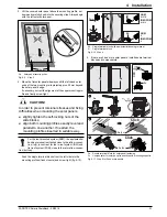
CAUTION!
Leaking vapour barriers can lead to building
damage.
●
Reseal the vapour barrier from the inside at
the penetration points of the connecting
pipes and cable.
CAUTION!
If plastic pipes are damaged, there is a risk that
they will break.
●
When cutting through the thermal insulation,
never damage the outer surface of the VA
Solaris connecting pipes.

