background image

x

 Installation

FA ROTEX Solaris DrainBack - 09/2016

19

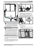
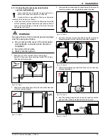
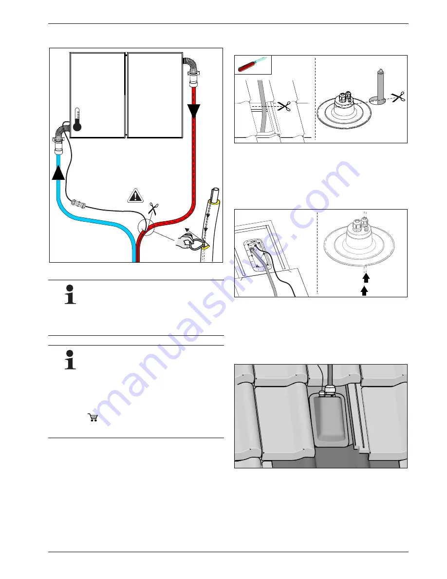
2. Lay the connection pipes up to the roof penetration and fix in 

position (e.g. with clamps).

3. Carefully cut open or cut off the thermal roof insulation under 

the roof penetration box so the return flow pipe (VA18 Solar) 
can be pulled out and laid with sufficient gradient to the roof 
penetration box.

4. Run the connecting pipes through the roof at the points pro-

vided. To ensure uninterrupted thermal insulation (also within 
the roof structure), the insulation must be resealed at the pen-
etration points (e.g. with adhesive tape).

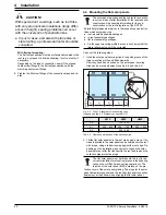
5. Cut off the thermal insulating hoses of the connecting pipes 

so that the pipes can be passed through the individual roof 
penetrations.

6. Pull the inflow pipe (top on the flat solar panel/VA15 Solar) as 

well as the return flow pipe (bottom on the flat solar 
panel/VA18 Solar) through the M32 screw fitting of the re-
spective roof penetration box. Next, push the equipotential 
bonding cable and the solar panel temperature sensor cable 
through the respective M16 glands from inside.

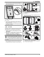
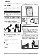
7.

For on-roof mounting:


Cover the roof penetrations.
– The roof tiles at the side and above must overlap the roof 

penetration.

– The corrugated flashing must overlap the roof tile under-

neath and be shaped to match the roof tile.

Fig. 4-4

Step 2

The connecting cable for the solar panel temper-
ature sensor is drawn into the heat insulation hose 
together with the inflow connecting pipe. At the joint 
of the inflow and return flow connecting pipes, it 

must be pulled out of the pre-fabricated connecting pipe 
CON… and routed along the return flow connecting pipe to 
the bottom panel connection.

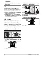
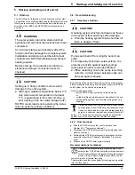
For flat roof mounting:

In order to keep the pipe laying as short as possible 
in the frost-endangered area (outdoors), ROTEX 

recommends installing two separate flat roof penetration 
boxes for two-way connection of the solar panel array for the 
roof penetration box of the inflow and return flow pipes.

With 3 and more solar panels, the two-way solar panel array 
must be connected with 2 flat roof penetration boxes. The 
CON FE (

 16 47 09) roof penetration box required for 

this is equipped with seals for the cable screw fittings. They 
must be converted to match the connection type.

T

K

Fig. 4-5

Step 5

Fig. 4-6

Step 6

Fig. 4-7

Step 7

Summary of Contents for H26P

Page 1: ...mpanies ROTEX Solaris Planning and installation instructions DrainBack solar system Valid for the following components Solaris V21P Solaris V26P Solaris H26P Solaris assembly packages GB Edition 09 20...

Page 2: ...ystems 7 3 3 2 System components for roof mounted systems ADM 9 3 3 3 System components for in roof systems IDM 11 3 3 4 System components for flat roof systems FDM 13 4 Installation 16 4 1 Transport...

Page 3: ...ir technical training and specialist knowledge Please read this manual carefully and thoroughly before proceeding with the installation and initial start up or modifi cation of the system Comply stric...

Page 4: ...levant accident pre vention regulations as well as the recognised safety related and occupational health rules 2 3 Use as intended The ROTEX solar system may only be used for solar supported heating o...

Page 5: ...condi tions of overvoltage category III and a residual current circuit breaker RCD with a reaction time 0 2 s Compare the mains voltage 230 V 50 Hz indicated on the nameplate with the supply voltage b...

Page 6: ...ne FLS Solaris FlowSensor flow rate measurement PS Solaris operating pump RPS4 Control and pump unit TK Solaris solar panel temperature sensor TR Solaris return flow temperature sensor TS Solaris stor...

Page 7: ...r unit of an air water heating pump Electronic control The fully electronic ROTEX Solaris R4 control unit ensures op timum utilisation of the solar heat hot water heating heating support and the obser...

Page 8: ...ble pipe clamps and connecting fittings Extension kit for feed line CON XV CON XV 80 16 42 64 L 8 m UV resistant thermally insulated feed line with integrated sensor cable pipe clamps cable connection...

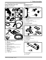
Page 9: ...5j Cable tie 5k Solar panel temperature sensor 5l n Extraction tool with inserts for 15 mm and 18 mm 5o Planning and installation instructions 5p Quick instructions 5q Cable connection fitting 5r Roof...

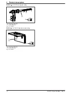
Page 10: ...escription FIX WD 16 47 03 for corrugated roofing FIX BD 16 47 04 for folded sheet metal roofing 12h Mounting profile beam 12i Quick instructions Fig 3 13 FIX WD 12j Mounting profile beam 12k Quick in...

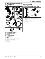
Page 11: ...n fitting 5e g Pipe clamps with hangar bolts 5h Single terminal block with equipotential bonding terminal 5i Single terminal block 5j Cable tie 5k Solar panel temperature sensor 5l n Extraction tool w...

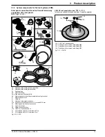
Page 12: ...in strip 10g Bottom left drip off sheet 10h Bottom right drip off sheet 10i Bottom left sight guard plate 10k Bottom right sight guard plate 10l Accessory bag 10m Accessory bag 10n Locking plate 10o...

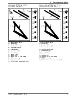
Page 13: ...al block with equipotential bonding terminal 5i Single terminal block 5j Cable tie 5k Solar panel temperature sensor 5l n Extraction tool with inserts for 15 mm and 18 mm 5o Planning and installation...

Page 14: ...exagon nut M8 6m Hexagon nut M8 with locking serration 6n Washer 6o Round head screw M8 6p Quick instructions Fig 3 22 Flat roof frame basic package FB V26P 6g 8x 6f 2x 6e 6 6 c d 6a 6p 6x 6x 10x 4x 1...

Page 15: ...ut M8 with locking serration 6n Washer 6o Round head screw M8 6p Quick instructions Fig 3 24 Flat roof frame basic package FB H26P 8 8d c 8b 8a 8g x 2 8f 8e 8p x 4 x 4 x 7 x 3 x 4 x 4 6h 6n 6k 6i 6m 6...

Page 16: ...ses and main switches remove cables and must be secured against inadvertent restarting The components must be stored in such a way that persons are not endangered by them The regulations in the respec...

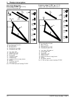
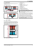
Page 17: ...nting rail 2b Solar panel securing clips 4 Solar panel 5 Solar panel connecting elbow return flow 6 Solar panel connecting elbow inflow 7 Sealing plug 8 Solar return flow pipe 9 Solar inflow pipe 10 S...

Page 18: ...of the inflow pipe is not more than 16 mm a continuous rise of the inflow pipe to the highest point as well as a continuous gradient to the warm water storage cylinder is ensured For pipe runs in whic...

Page 19: ...M16 glands from inside 7 For on roof mounting Cover the roof penetrations The roof tiles at the side and above must overlap the roof penetration The corrugated flashing must overlap the roof tile und...

Page 20: ...gs such as roof tiles with very pronounced undulations large differ ences in height sealing problems can occur with the universal roof penetration box In such cases and also with plane tiles or slate...

Page 21: ...tep 3 CAUTION In order to prevent torsional stresses and fixing difficulties when mounting the solar panels slightly tighten the self locking nuts of the slide blocks align both mounting profiles exac...

Page 22: ...e system Always fit the expansion joints to the flat solar panels with extreme caution Bring the next flat solar panel in alignment with the connection pipes of the previous flat solar panel when push...

Page 23: ...Insert the sealing plugs into the open solar panel connection pipes until the retaining clamps audibly click in place These instructions only describe the pipe laying for al ternate end connection wit...

Page 24: ...sing cable ties Then connect the silicone covered cable inside the roof to the connection cable of the solar panel temperature sensor of the control and pump units WARNING The equipotential bonding do...

Page 25: ...nducted by ROTEX authorised and trained heating experts Before start up the protective conductor re sistance and proper connection must be checked CAUTION Setting up in frosty conditions can result in...

Page 26: ...al in compliance with the respective na tional regulations of the country of use is the responsi bility of the user owner Disassembly of the system handling of coolant oil and other parts may only be...

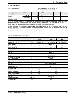
Page 27: ...EC for correct selection of products for your application contact your dealer Depending on your application and the product selected an additional supplementary heater may have to be installed Tab 6...

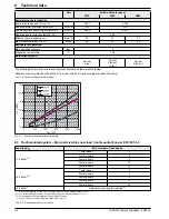
Page 28: ...anently standstill proof and thermo shock tested Minimum collector yield above 525 kWh m2 per year with 40 cloud coverage location W rzburg Tab 6 2 Technical Data Flat Solar Panel Unit Solaris flat so...

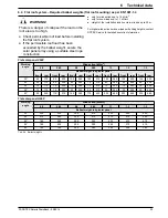
Page 29: ...ssible roof load has been exceeded by the ballast weight secure the solar panel array using a suitable steel rope construction Working angle Wind action kN m2 0 5 0 65 0 8 0 95 1 1 1 2 1 3 Ballast wei...

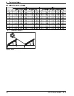
Page 30: ...5 60 6 50 7 21 7 48 7 70 3 64 4 23 4 69 4 86 5 00 50 5 11 5 87 6 46 6 68 6 85 3 32 3 82 4 20 4 34 4 45 48 4 72 5 37 5 86 6 04 6 18 3 07 3 49 3 81 3 93 4 01 46 4 41 4 97 5 38 5 53 5 63 2 86 3 23 3 50 3...

Page 31: ...ial bonding 24 Roof penetration 19 Solar panel temperature sensor 24 M Mounting profile connector 8 Mounting profile rail 7 O Operating mode 7 Outer layer of storage tank 7 P Parallel connection 17 Pr...

Page 32: ...ROTEX FA ROTEX Solaris DrainBack Subject to change and correction 008 1628844_00 09 2016...

Reviews: