background image


RTX-IOM-PRODUCT-YY


Page 

121

 of 

131


www.rotexautomation.com 


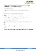
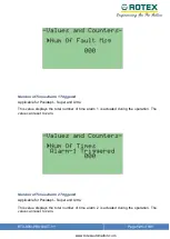
Number of Times Alarm 1 Triggered  

Applicable for Posidapt 

– Super and Ultra  

This value displays the total number of  time alarm 1 is actuated during the operation. The 
value can reset to zero. 


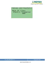
Number of Times Alarm 2 Triggered  

Applicable for Posidapt 

– Super and Ultra  

This value displays the total number of  time alarm 2 is actuated during the operation. The 
value can reset to zero. 

Summary of Contents for Posidapt Expert

Page 1: ...RTX IOM PRODUCT YY Page 1 of 131 www rotexautomation com SMART POSITIONER POSITIONER Installation Operation and Maintenance Manual...

Page 2: ...nting Positioner on a Rotary Actuator 26 6 4 Mounting Positioner with bearing assembly on a Rotary Actuator 29 6 5 Mounting Positioner with the bearing assembly on a Control Valve 32 6 6 Remote Mounti...

Page 3: ...n com 8 3 4 Diagnostics and Setup 87 8 3 5 Diagnostics 103 8 4 Parameter Overview DTM 123 8 4 1 Device Information 123 8 4 2 Online Statistics 128 8 4 3 Valve Offline Test 130 9 Alert and Error Messag...

Page 4: ...e operated only by personnel qualified for the specific task in accordance with the relevant documentation in particular its warning notices and safety instructions Qualified personnel are those who b...

Page 5: ...e 1 year except as otherwise stated ROTEX warranty will not cover the products that the product have been subjected to abuse accident alteration modification tampering negligence misuse faulty install...

Page 6: ...ing menu diagnostics and alarms Quick calibration using two push buttons IP66 Pre fitted gauge enclosed in IP66 enclosure ensure lifetime guaranty and reliability Electronics Encapsulated electronic p...

Page 7: ...RTX IOM PRODUCT YY Page 7 of 131 www rotexautomation com 1 2 Posidapt Series...

Page 8: ...acting Failsafe o Failsafe or stay put fail freeze Actuator Travel Range Linear o 0 position can start anywhere 3 to 200 mm stroke other strokes on request Rotary o 0 position can start anywhere max 3...

Page 9: ...lon Polycarbonate cover o 2 Epoxy coated anodised aluminium housing cover with Makrolon see through window o 3 Explosion proof aluminium housing cover with toughened glass see through window o 4 Explo...

Page 10: ...Alarm module 0 08 kgs 0 2 lbs Pneumatics Supply pressure o 1 4 to 8 bar 0 to 14 psi 10 bar on request Capacity with 4 bar 60 psi o 1 to 41 Nm h 0 5 to 23 scfm servo controlled orifice Consumption wit...

Page 11: ...em both with or without HART signal Minimum Signal o 3 6 mA Current max o 36 mA with overload protection Load Voltage o 9 7 VDC 20 mA max 30 VDC Impedance o 485 at20 mA Wire Cross Section o Screw term...

Page 12: ...ly Voltage o 12 to 30 VDC Total Operating Range o 3 6 to 21 mA Transmission Error o 0 3 Influence of temperature o 0 35 10 K Alarm Module Supply Voltage o 12 to 30 VDC Max Supply Voltage o 35 VDC Sign...

Page 13: ...TX IOM PRODUCT YY Page 13 of 131 www rotexautomation com Communication HART 5 7 Foundation Field bus Profibus PA Certification Atex o II 2GD Ex ia IIC T6 Gb o II 2GD Ex d IIC T6 Gb Safety o Up to SIL...

Page 14: ...On screen display of diagnostics alarms and error messages Modular design with encapsulated electronics a Fewer modules make it easy to install operate and maintain b Fewer numbers of internal compon...

Page 15: ...ty during calibration and testing Communication a ROTEX POSIDAPT is compatible with Foundation fieldbus Profibus and HART version 5 7 b It is also compatible with DTM framework version 1 2 1 c DTM and...

Page 16: ...131 www rotexautomation com Identification of the product Product code breakdown R T X 7 1 1 2 G H P 4 R R M 0 3 SERIES MODEL ENCLOSURE SERVO PORT CONNECTIONS COMMUNICATION MODULE CABLE ENTRY TEMPERAT...

Page 17: ...RTX IOM PRODUCT YY Page 17 of 131 www rotexautomation com 4 Bock Diagram...

Page 18: ...RTX IOM PRODUCT YY Page 18 of 131 www rotexautomation com 5 Dimensional Drawing...

Page 19: ...LD BE TAKEN TO AVOID WATER SEEPAGE CONFIRM THE AREA IS NON HAZARDOUS BEFORE OPENING THE COVER OF THE ENCLOSURE FOR MAKING ELECTRICAL CONNECTIONS THE PLUGS GIVEN ALONG WITH BOX ARE TO BE REMOVED AND ME...

Page 20: ...d cable glands and plugs to be used The plugs given along with box are to be removed and metallic plug to be used Operating temperature range should not exceed then the mentioned on the tag plate Avoi...

Page 21: ...RTX IOM PRODUCT YY Page 21 of 131 www rotexautomation com Basic layout Smart positioner with Globe valve Smart positioner with Rotary Actuator...

Page 22: ...ed for the installation of the smart Positioner on the linear actuator Table 1 Sr No Part description Qty Note 1 M6 Nut 1 For fixing scale 2 Hex bolt M6 x 35 mm 1 For fixing scale 3 Linear Scale 1 4 M...

Page 23: ...RTX IOM PRODUCT YY Page 23 of 131 www rotexautomation com Figure 1 Linear scale assembly Figure 2 Attaching the linear scale and the mounting bracket...

Page 24: ...3 Assemble the linear scale assembly as shown in the figure 1 4 Attach the mounting bracket to the Positioner as shown in the figure 2 also attach the linear scale to the shaft of the Positioner 5 Mou...

Page 25: ...t in the slot in the scale and lock it using the locking spring as shown in fig 3 Make sure that the scale is horizontal when calibrating the positioner Secure the bolts firmly and proceed for calibra...

Page 26: ...of components required for the installation Table 2 Sr No Part description Quantity Note 1 Std Mounting bracket 1 2 Plain washer M6 4 For attaching Positioner to bracket 3 Hex Bolt M6 x 12 4 For attac...

Page 27: ...RTX IOM PRODUCT YY Page 27 of 131 www rotexautomation com Figure 4 Attaching the coupling and the bracket to the positioner Figure 5 Inserting coupling in shaft of the rotary actuator...

Page 28: ...y using grub screws as indicated in the figure above 3 The assembly is then mounted on the actuator refer figure 6 below while taking care that the shaft enters in the slot of the actuator pinion 4 As...

Page 29: ...list of components required for the installation Table 3 Sr No Part description Quantity Note 1 Shaft and bearing assembly 1 2 Grub screw M6 X 45 4 For attaching Positioner to bracket 3 Nut M6 4 For a...

Page 30: ...RTX IOM PRODUCT YY Page 30 of 131 www rotexautomation com Figure 7 Attaching coupling and bracket to positioner...

Page 31: ...y using grub screws as indicated in the figure above 8 The assembly is then mounted on the actuator refer figure 8 below while taking care that the shaft enters in the slot of the actuator pinion 9 As...

Page 32: ...ge 32 of 131 www rotexautomation com 6 5 Mounting Positioner with the bearing assembly on a Control Valve This section provides information regarding mounting of smart Positioner on a linear actuator...

Page 33: ...automation com Table 4 Sr No Part description Quantity Note 1 Smart positioner 1 2 Hex bolt M6 x 30 2 Mounting positioner on valve 3 Std Mounting bracket 1 4 Control Valve 1 5 Linear scale assembly 1...

Page 34: ...exautomation com The figure 9 below gives a detailed and labelled refer table 4 view for mounting the positioner with the bearing and shaft assembly on a control valve Figure 9 Mounting of positioner...

Page 35: ...e 1 Fix the positioner along with the mounting bracket at the centre of the control valve depending on the stroke of the control valve Insert the shaft in the slot in the scale and lock it using the l...

Page 36: ...ecial version of the same includes up to 30m of cables available on request ROTEX shielded cable and circular connectors ensure better connectivity Ideal for extreme environments and harsh conditions...

Page 37: ...d Mounting bracket 1 3 M5 nut 2 For attaching Remote Mount to bracket 4 M5 Plain washer 2 For attaching Remote Mount to bracket 5 Hex Bolt M5 x 20 2 For attaching Remote Mount to bracket 6 Grub screw...

Page 38: ...igure 10 above 12 Attach the coupling securely using grub screws as indicated in the figure above 13 The assembly is then mounted on the actuator refer figure 11 below while taking care that the shaft...

Page 39: ...RTX IOM PRODUCT YY Page 39 of 131 www rotexautomation com Figure 11 Mounting the Positioner on a rotary actuator...

Page 40: ...RTX IOM PRODUCT YY Page 40 of 131 www rotexautomation com 6 8 Mounting remote unit on a Control Valve This section gives the instructions needed for mounting the Remote Unit on a Control valve...

Page 41: ...RTX IOM PRODUCT YY Page 41 of 131 www rotexautomation com Figure 12 Detailed mounting of the remote unit on a control valve...

Page 42: ...unting Instructions Assemble the linear scale assembly as shown in the figure 1 Attach the mounting bracket to the Remote unit Fix the Remote Unit along with the mounting bracket at the centre of the...

Page 43: ...IOM PRODUCT YY Page 43 of 131 www rotexautomation com 6 9 Unfavourable mounting conditions The ROTEX smart Positioner can be mounted in all orientations except the one where the exhaust is facing upwa...

Page 44: ...RTX IOM PRODUCT YY Page 44 of 131 www rotexautomation com 7 Electrical Connection...

Page 45: ...RTX IOM PRODUCT YY Page 45 of 131 www rotexautomation com 8 User Interface 8 1 Menu Structure Posidapt Expert...

Page 46: ...RTX IOM PRODUCT YY Page 46 of 131 www rotexautomation com...

Page 47: ...47 of 131 www rotexautomation com 8 2 Display Screen Process Display with Position Process Display with Set point and Position Press Up or Down key for 5 second to display both set point and position...

Page 48: ...d cannot be changed Linear Turn Use this parameter value for a linear actuator with mechanism movement parallel to the movement of the actuator The device compensates the nonlinearity caused due to th...

Page 49: ...r Function Applicable for Posidapt Modern Expert Super Ultra and IPST Parameter used for a defining actuator function Double acting Factory default Use this parameter value for double acting actuator...

Page 50: ...ure Applicable for Posidapt Modern Expert Super Ultra and IPST This parameter is used to set the temperature unit The selected temperature unit is then also applicable for all other temperature based...

Page 51: ...re unit is then also applicable for all other pressure based parameters bar Factory default This sub parameter value sets the pressure unit to bar psi This sub parameter value sets the pressure unit t...

Page 52: ...hich operating the device should start in after restart or input signal failure Auto Factory default This parameter will start the device in auto mode Manual This parameter will start the device in ma...

Page 53: ...ry default This parameter will close the valve Open This parameter will open the valve Stay put not applicable for IPST This parameter will lock the valve in current position Set point not applicable...

Page 54: ...f the device is not calibrated initially only value Auto1 is allowed for calibration Auto1 Recommended It sets all the parameter which needs to be calibrated in order for valve system to operate as de...

Page 55: ...and IPST This parameter initializes timeout for calibration 60 Seconds Set calibration time value to 60 seconds 120 Seconds Set calibration time value to 120 seconds 180 Seconds Set calibration time v...

Page 56: ...This parameter is used to reset the custom values of parameters set by user to factory setting default values Counter reset This parameter is used to reset all counter values to factory reset values R...

Page 57: ...rotexautomation com Write Protect Applicable for Posidapt Modern Expert Super Ultra and IPST This parameter is used for write protect for HART communication Off This parameter disable write protect O...

Page 58: ...meter is used to set the current range The selection of the current range depends on the type of connection 4 20 mA Factory default Use this parameter when the supply input signal current range is fro...

Page 59: ...r Ultra and IPST This parameter used to set the start range for input signal It allows limiting the effective start set point Off Factory Default This parameter disable split range minimum feature Cus...

Page 60: ...per Ultra and IPST This parameter used to set the end range for input signal It allows limiting the effective end set point Off Factory Default This parameter disable split range maximum feature Custo...

Page 61: ...ed to set the action of set point direction This parameter is used to reverse the set point direction of action from forward to reverse vice versa Counter clockwise This parameter is use to set the ac...

Page 62: ...irection of action for display The set point direction of action for display is used to reverse the direction of action from forward to reverse vice versa Increment This parameter is use to set the se...

Page 63: ...IPST This parameter is used to set the Position transmitter output direction depending on position 10 Increment Factory default This parameter is use to set the position transmitter output to increme...

Page 64: ...t Modern Expert Super Ultra and IPST This parameter selects functionality of Input pin value for function of input Off Factory default Disable state of input function Normally Open NO Detect logic 1 o...

Page 65: ...ure or temperature switches can be read over the communication interface or fed through a logical OR combination with other messages to trigger the fault message output Block Configuration NO NC This...

Page 66: ...gulates to the value specified in parameter Zero point soft stopper Move Valve position to user set point NO NC not applicable for IPST If input 1 is activated then the actuator regulates to the value...

Page 67: ...t Modern Expert Super Ultra and IPST This parameter selects functionality of Input pin value for function of input Off Factory default Disable state of input function Normally Open NO Detect logic 1 o...

Page 68: ...e switches can be read over the communication interface or fed through a logical OR combination with other messages to trigger the fault message output Block Configuration NO NC This parameter value c...

Page 69: ...lue specified in parameter Zero point soft stopper Move Valve position to user set point NO NC not applicable for IPST If input 2 is activated then the actuator regulates to the value set by user The...

Page 70: ...ly to input signal changes overshoots occurs while achieving the target position Quick In order to optimize the control performance the device responds quickly to input signal changes small overshoots...

Page 71: ...Modern Expert Super Ultra and IPST This parameter is used to adjust the dead band of the controller Auto Factory default This parameter continuously adaptively adjusts the dead band to the requiremen...

Page 72: ...ximum force of the actuator Off This parameter will deactivate the tight shut off function at close position This parameter controls 0 0 start position of the device the device is in controlled state...

Page 73: ...rameter will deactivate the tight shut off function at open position This parameter controls 100 0 end position of the device the device is in controlled state Custom This parameter used for setting t...

Page 74: ...e start position is same as the actual start position of the actuator determined during auto calibration Custom This parameter is used to cut off start position 0 0 unusable range of the control valve...

Page 75: ...tion is same as the actual end position of the actuator determined during auto calibration Custom This parameter is used to cut off end position 100 0 unusable range of the control valve It is the per...

Page 76: ...is mode the start zero mechanical position is the same as the actual start position of the actuator determined during auto calibration Custom The start zero position can be configured to desired value...

Page 77: ...ult In this mode the end mechanical position is the same as the actual end position of the actuator determined during auto calibration Custom The end position can be configured to desired value This a...

Page 78: ...100 0 between the actual mechanical stops of the actuator irrespective of the Zero point soft stopper End point soft stopper parameters Scale This parameter value shows the mechanical position from 0...

Page 79: ...RTX IOM PRODUCT YY Page 79 of 131 www rotexautomation com...

Page 80: ...r control servo valve spool forward sensitivity Auto It is the minimum spool movement to achieve minimum set point change in forward direction Custom It sets the sensitivity aggressiveness of the posi...

Page 81: ...Auto It is the maximum forward velocity of the positioner to achieve the set point without being overshot Custom It sets the velocity of the positioner Not recommended to change it manually The value...

Page 82: ...y Auto It is the minimum spool movement to achieve minimum set point change in reverse direction Custom It sets the sensitivity aggressiveness of the positioner not recommended to change manually The...

Page 83: ...ivity Auto It is the maximum reverse velocity of the positioner to achieve the set point without being overshot Custom It sets the velocity of the positioner Not recommended to change it manually The...

Page 84: ...seven pre defined four user defined characteristics Sr no Valve characteristics Values 1 Linear Factory default Linear 2 Square 01 25 3 Square 01 33 4 Square 01 50 5 Square root 25 01 00 6 Square roo...

Page 85: ...l curve with 20 linear segments which models the valve characteristic The difference between digital and mechanical set point is digital set point are set through keypad or DTM whereas mechanical set...

Page 86: ...point 5 6 User defined set point 6 7 User defined set point 7 8 User defined set point 8 9 User defined set point 9 10 User defined set point 10 11 User defined set point 11 12 User defined set point...

Page 87: ...lue exceeds one of the three configurable limit thresholds Threshold Limit 1 Use this sub parameter to set the factor for the formation of limit threshold 1 Off Factory default This parameter value do...

Page 88: ...one of the three configurable limit thresholds Threshold Limit 1 Use this sub parameter to set the factor for the formation of limit threshold 1 Off Factory default This parameter value does not trigg...

Page 89: ...to Custom The current value is displayed in the End set point shift in Values and Counters under Counter Thresholds and Trends The device triggers a fault message if the current value exceeds one of...

Page 90: ...Posidapt Super and Ultra This parameter is used to determine the basic control accuracy of the valve The current dead band value is displayed in the Dead band in Values and Counters under Counter Thr...

Page 91: ...ed The value can be set from 0 1 to 20 0 Threshold Limit 3 Use this sub parameter to set the factor for the formation of limit threshold 3 Off Factory default This parameter value does not trigger any...

Page 92: ...figurable limit thresholds Auto Factory default This sub parameter is set to Auto if the device is auto calibrated The time constant is determined from the calibration process by actuating times open...

Page 93: ...rse changes in the valve position the so called slip jumps let the device close at too large static friction If slip jumps are detected the filtered step height is saved as a de jamming value If slip...

Page 94: ...r and Ultra This parameter is used for steady state load measurement which is especially significant for single acting actuators since you can use it estimate the actuator spring force and spring cond...

Page 95: ...f This parameter value does not trigger any message or alarm Custom The threshold 3 fault message is displayed when the limit threshold 3 is exceeded The value can be set from 0 0 to 10 0 bars Lower T...

Page 96: ...old 2 The device triggers a fault message if the current temperature inside the enclosure undershoots threshold 2 Off This parameter value does not trigger any message or alarm Custom This sub paramet...

Page 97: ...closure exceeds threshold 1 Off This parameter value does not trigger any message or alarm Custom This sub parameter value is used to monitor the upper limit temperature Set the threshold in a range f...

Page 98: ...the current value undershoots one of the three configurable limit thresholds Threshold Limit 1 This parameter is used to set the pressure threshold 1 The device triggers a fault message if the current...

Page 99: ...sensor on the main circuit board The maximum recorded value is displayed in the Maximum pressure recorded diagnostics parameter The device triggers a fault message if the current value overshoots one...

Page 100: ...0 0 bar Load for Opening Applicable for Posidapt Super and Ultra This parameter is used to determine minimum pressure required to open the valve from full close position The actual value auto calibrat...

Page 101: ...ter is used to set threshold 3 for the deviation in Load for Opening of current value from the reference value Off This parameter value does not trigger any message or alarm Custom This parameter is u...

Page 102: ...he average of the measure position is recorded in the corresponding working range The following are the actuating range 0 10 20 30 40 50 60 70 80 90 100 60 50 40 30 20 10 0 10 20 30 40 50 60 70 60 50...

Page 103: ...Threshold Limit 1 Use this sub parameter to set the limit threshold 1 Off This parameter value does not trigger any message or alarm Custom The threshold 1 fault message is displayed when the limit th...

Page 104: ...gnostics parameter The device triggers a fault message if the current value exceeds one of the three configurable limit thresholds Threshold Limit 1 Use this sub parameter to set the limit threshold 1...

Page 105: ...exceeds one of the three configurable limit thresholds The current value is displayed in the Position Average diagnostics parameter Monitoring Time This parameter is used to set the time interval to...

Page 106: ...ld 2 in percent The device triggers a fault message if the difference between the position average and the reference average exceeds threshold 2 The value can be set from 0 1 to 100 0 Threshold Limit...

Page 107: ...not trigger any message or alarm Custom The device triggers a fault message if average direction change value exceeds set threshold value The value can be set up to 100000000 Average Direction Change...

Page 108: ...Posidapt Modern Expert Super Ultra and IPST This value displays the set point current input loop current input signal Number of Strokes Applicable for Posidapt Modern Expert Super Ultra and IPST The...

Page 109: ...incremented every hour as soon as electric auxiliary power is supplied to the device This value displays number of operational hours of device Actuating Time Open Applicable for Posidapt Modern Expert...

Page 110: ...apt Modern Expert Super Ultra and IPST This value displays the actuating time required for close down direction determined during auto calibration process The unit is seconds Pneumatic Leak Applicable...

Page 111: ...rmined deviation from the actual model response The actual position course is compared with the expected position course for this purpose This comparison helps in drawing a conclusion about the correc...

Page 112: ...e from full close position Value is automatically determined during auto calibration process Zero Set point Shift Applicable for Posidapt Super and Ultra This value displays the current displacement o...

Page 113: ...splays the current displacement of the upper hard end stops open with respect calibration value The sub parameter Open in Tight shut off parameter is set to Custom to determine this value else Off is...

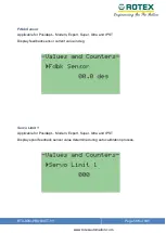
Page 114: ...e for Posidapt Modern Expert Super Ultra and IPST Display feedback sensor value determined during auto calibration process in deg Fdbk Sensor Limit 2 Applicable for Posidapt Modern Expert Super Ultra...

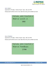
Page 115: ...Sensor Applicable for Posidapt Modern Expert Super Ultra and IPST Display feedback sensor current value in deg Servo Limit 1 Applicable for Posidapt Modern Expert Super Ultra and IPST Display spool f...

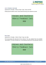
Page 116: ...le for Posidapt Modern Expert Super Ultra and IPST Display spool feedback sensor value determine during auto calibration process Servo Feedback Applicable for Posidapt Modern Expert Super Ultra and IP...

Page 117: ...a and IPST Display spool feedback sensor value determine during auto calibration process Dead band Applicable for Posidapt Modern Expert Super and Ultra This value displays the dead band of the contro...

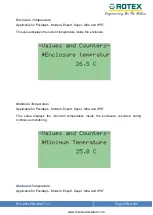
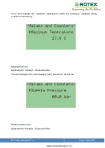
Page 118: ...d IPST This value displays the current temperature inside the enclosure Minimum Temperature Applicable for Posidapt Modern Expert Super Ultra and IPST This value displays the minimum temperature insid...

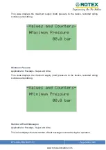
Page 119: ...isplays the maximum temperature inside the enclosure recorded during continuous monitoring Supply Pressure Applicable for Posidapt Super and Ultra This value displays the current supply inlet pressure...

Page 120: ...ring continuous monitoring Minimum Pressure Applicable for Posidapt Super and Ultra This value displays the minimum supply inlet pressure to the device recorded during continuous monitoring Number of...

Page 121: ...Super and Ultra This value displays the total number of time alarm 1 is actuated during the operation The value can reset to zero Number of Times Alarm 2 Triggered Applicable for Posidapt Super and Ul...

Page 122: ...RTX IOM PRODUCT YY Page 122 of 131 www rotexautomation com...

Page 123: ...cording to their function application It can have up to 32 random ASCII characters Applicable with HART 7 Installation Date Applicable for Posidapt Expert Super Ultra and IPST Enter a date when the de...

Page 124: ...ld there is no recommendation for this field Device Type Applicable for Posidapt Expert Super Ultra and IPST Type of connected device Model of the device Expert Super Ultra IPST Hart Revision Applicab...

Page 125: ...ld can be used freely and helps to identify the manufacturer of the valve It can have up to 32 random ASCII characters Model Applicable for Posidapt Expert Super Ultra and IPST This field can be used...

Page 126: ...to enter the description of the solenoid valve mounted It can be used to enter model manufacturer rating etc Volume Booster Quick Exhaust valve Applicable for Posidapt Expert Super Ultra and IPST This...

Page 127: ...and Quick Exhaust Valve Type 1 Volume booster and quick exhaust valve size up to 1 2 Combination of Volume Booster and Quick Exhaust Valve Type 2 Volume booster and quick exhaust valve size above 1 2...

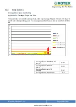
Page 128: ...ily average dead band in percentage for past 24 hours 30 days 12 month and corresponding years This Average dead band value can be read from DTM or DD Average Dead band Past 24 Hours 0 48 Average Dead...

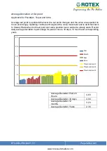
Page 129: ...hroughout the valve movement and is switched back to Steady State when both set point and valve position have reached a steady state Record daily average deviation in percentage for past 24 hours 30 d...

Page 130: ...ysis Dynamic Loop Test Dynamic loop test provides information on dynamic dead band of the valve assembly The valve will be open or close with the change in the input set point Valve Characteristic Tes...

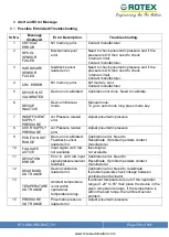
Page 131: ...URE Air Pressure related error Adjust pneumatic pressure 8 OVER SUPPLY PRESSURE Air Pressure related error Adjust pneumatic pressure 9 POSITION OUT RANGE Device not calibrated Feedback sensor related...

Reviews: