5
x
Control unit operation
29
FA ROTEX Solaris RPS3 25M - 03/2010
5
Control unit
5.1
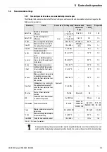
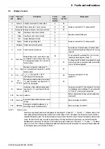
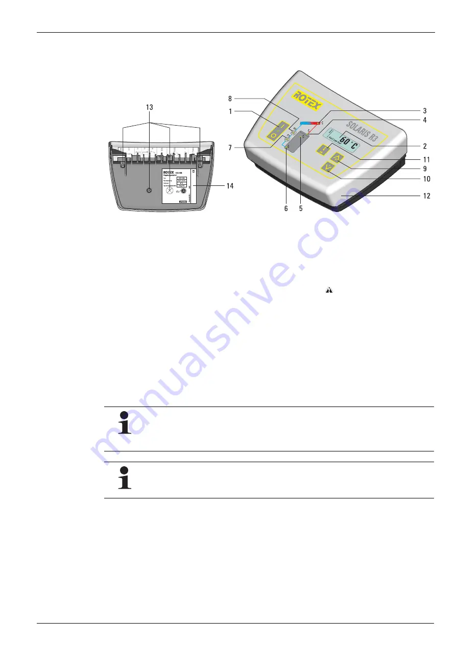
Operating and display elements
5.2
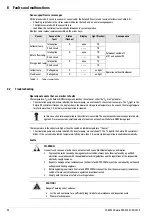
Controller operating principle
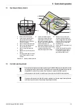
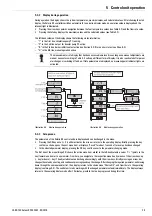
1
Main switch with indicator light
2
Temperature and parameter display
(energy saving function: display
illumination switches off 10 minutes
after the last keypress)
3
Light for collector temperature display
4
Light for solar flow temperature and
flow rate measurement (FLS)
5
Light for storage tank temperature
display
6
Light for solar return flow temperature
display
7
Operating condition light for circulation
pump P1 (lights up when the pump is
operating)
8
Function only available if optional
booster pump is installed: Operating
condition light for booster pump P2
(lights up when the pump is operating)
9
Up arrow for moving the temperature or
parameter display up by one
setting/increasing parameter settings
10
Down arrow for moving the temperature
or parameter display down by one
setting/decreasing parameter settings
11
Information key for accessing the
information level (displays measured
values, maximum values and calculated
values) and OK key for confirming and
storing settings in the setting menu
12
Controller housing
13
Locking screws for unit housing (at rear)
14
Rating plate
Unit may only be opened by specialists.
Before opening the unit, disconnect it
from the power supply and secure it
against being switched back on!
Illustration 5-1 Operating and display elements
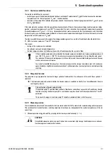
Because of constant improvements aimed at optimum use of the RPS3 25M system, the Solaris R3 controller
has been equipped with an update function. Consequently some of the functions described in this chapter are
only applicable to certain software versions. These functions are separately identified by symbols.
Software updates to the Solaris R3 controller may only be carried out by the ROTEX service technician.
The mains switch disconnects the Solaris R3 controller completely from the mains supply. Operating the mains
switch requires greater pressure than actuating the operating buttons does.

