3
x
Installation
13
FA ROTEX Solaris RPS3 25M - 03/2010
3.2
System design
Calculation of the piping network is necessary to ensure that the circulation pump and the connection pipes are correctly dimen-
sioned.
We recommend the following data as rough values:
1.
Nominal flow rate per solar panel = 100 l/h
2.
Size of the collector array and storage tank volume:
– Maximum of 5 solar collectors per 500 l storage tank volume.
– Maximum of 10 solar panels per row.
3.
When installing several rows of solar panels, there should be the same number of panels in each row as far as possible, and
they should be connected according to the Tichelmann principle.
4.
Route feed connections for several rows of solar panels in a continuous upward gradient to the point where they are
combined to form a common feed pipe.
5.
Measuring the pressure drops:
a)
Resistance of the collector array (chapter 8.3, Image 8-3).
The diagram shows the pressure drop in a row of solar panels including the connection fittings, with and without the
influence of the connection pipes from connection set CON X20 25M. The influence of the plastic connection pipes
available from ROTEX depending on the required length can be calculated precisely with the help of Image 8-6 in chapter
8.3.
b)
Resistance of the flow connection on the hot water storage tank (chapter 8.3, Image 8-4).
The diagram allows you to calculate the pressure drop at a recommended flow connection when the FlowGuard (FLG) is
fully opened. The FlowGuard is required for hydraulic balancing on each flow connection in systems with several hot
water storage tanks.
c)
Resistance of the return connection on the hot water storage tank (chapter 8.3, Image 8-5).
The diagram can be used to calculate the pressure drop at a CON RA 25M return connection set fitted to a hot water
storage tank. In the case of several storage tanks connected in series, the pressure drop is calculated as the sum of the
partial resistance values depending on the respective flow rates.
d)
Resistance of the feed and return connection pipes.
The pressure drop from the partial lines not already calculated under a) to d) is calculated according to the classical
pipeline network calculation methods, depending on the required pipeline lengths and the individual resistances of
moulding parts.
6.
Pump capacity
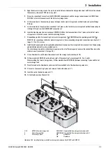
In order to overcome the sum of all resistance values calculated in point 5, the capacity of the pump must be such that it
supplies a sufficient pressure boost at the required nominal flow rate "Q
1
" (total number of solar panels x 100 l/h). This total
pressure drop in the collector circuit will ideally be equivalent to the pump delivery "H
1
" at work step "A" (Image 3-4).
At the same time, the delivery capacity "H
0
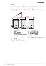
" of the pump must be greater than the maximum static pressure in the system,
which is calculated by taking the total height "H" of the system (see Image 2-1) in metres x 100 mbar.
Under certain conditions, it may be advisable to connect a second pump (booster pump) in series with the circulation pump
to allow faster filling of the system.
Whenever you select a pump, ensure that the pump:
– is suitable for reverse flow in switched-off state.
– is suitable for the permanent transport of water containing oxygen.
– is arranged in such a way that the necessary pre-pressure which may be needed is ensured via the filling level of the
water in the hot water storage tank.
CAUTION!
When solar panels are installed in areas where there is a danger of frost, connection pipes of the Solaris system
which lie outside may freeze, causing malfunctions and damage to the Solaris system.
•
Ensure that pipe runs in the open air are kept as short as possible.
•
Longer pipe runs in the open air (e. g. in the case of installation on a flat roof) must be specially insulated
or protected against frost by other appropriate means.
•
If necessary, a separate feed line must be routed from each row of solar panels affected by the risk to the
respective storage tank battery.


