6
x
Faults and malfunctions
44
FA ROTEX Solaris RPS3 25M - 03/2010
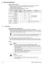
Sensor-specific error messages
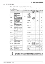
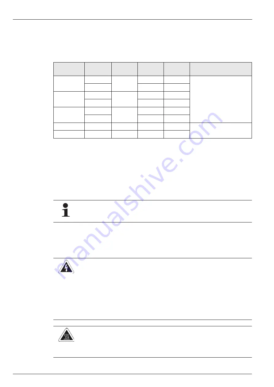
With a break or short circuit in a sensor or sensor cable, the Solaris R3 control unit reacts as follows (see Table 6 -2):
– A flashing code letter in the status column indicates the fault, and an error message appears.
– The light associated with the sensor flashes.
– In addition, the control unit automatically intervenes in system operation.
All other sensor values remain accessible via the arrow keys.
Table 6 -2
Table of sensor faults
6.2
Troubleshooting
Operational events that are similar to faults
The temperature T
S
in the Solaris DHW storage tank reaches the value set under the "T
S
max" parameter:
– The circulation pump and, where installed, the booster pump, are switched off, the system runs empty. The T
S
light in the
Solaris R3 control unit flashes, the display shows the measured storage tank temperature. As soon as the storage tempera-
ture falls more than 2 K, normal system operation is resumed.
The temperature in the collector is higher than the switch-on inhibit temperature "T
K
perm"
– The circulation pump and, where installed, the booster pump, are switched off. The T
K
light in the Solaris R3 control unit
blinks. If the set switch-on inhibit temperature falls by more than 2 K, normal system operation is enabled automatically.
Faults
Sensor
Cause of the
fault
Status
(flashes)
Display
Light (flashes)
Consequence
Collector temp.
Interruption
K
uuuu
TK
Permanent switch-off
of P1 and optional P2
Short circuit
––––
TK
Return flow temp.
Interruption
R
uuuu
TR
Short circuit
––––
TR
Storage tank temp.
Interruption
S
uuuu
TS
Short circuit
––––
TS
Inflow temp.
Voltage drop
V
––––
no light
Operation without FlowSensor
FlowSensor
Voltage drop
D
––––
no light
In this case, short-term evaporation in the collectors is possible. The unpressurised steam escapes into the stor-
age tank. On rare occasions, small amounts of steam can escape from the Solaris DHW storage tank.
WARNING!
Live parts can cause an electric shock on contact and cause life-threatening burns and injuries.
•
To prevent hazards caused by damaged electrical cables, always have them replaced by a qualified
electrician in compliance with the applicable electrical guidelines and the regulations of the responsible
electricity supply company.
•
Repairs to damage on live components on the Control unit RPS3 25M may only be carried out by authorised
and approved heating engineers.
•
Before beginning repair work, Control unit RPS3 25M disconnect the from the power supply (remove fuse,
switch off main switch) and secure against unintentional restart.
•
Comply with the relevant safety at work regulations.
CAUTION!
Danger of burning on hot surfaces.
•
Let the unit cool down for a sufficiently long time before maintenance and inspection work.
•
Wear protective gloves.

