5
x
Operation
39
FA ROTEX Solaris RPS3 P2 - 06/2012
The following information will assist with calculating the settings and will guarantee optimum heat yield with low power
consumption:
• Set the cut-in temperature difference "Delta T on" so the system remains operating after start-up under even solar radiation
conditions and does not shut down immediately the solar panels cool down after removing heat. The lower the selected value
can be the longer operation times and therefore the greater the achievable heat yields. If the cut-in temperature difference
is set too low the solar panels will cool down as soon as the pumps are started enough to fall below the cut-out temperature
difference.
Î
The pumps will shut down immediately and less heat will be obtained at high power consumption.
• Set the cut-out temperature difference "Delta T off" so the available heat output at the cut-out point is higher than the
electrical power required to operate the pumps.
Î
Because the power consumption of the pumps is virtually independent of the area of the solar panels but the available
heat output depends directly on the number of solar panels, the parameter value is set higher with fewer solar panels
and lower with more solar panels.
• Set the cut-in delay for the tank circulation pump "Time PsE" so hot water is at the RPWT1 plate heat exchanger until the
tank circulation pump starts.
• The maximum storage tank temperature "T
S
max" is set appropriately for the individual requirements. The higher the
parameter value the higher the available heat storage capacity and therefore the potential output of the solar system.
The cut-in protection temperature "T
K
zul" is preset at the factory to prevent noise and steam formation. The Solaris control
system only switches on the pumps if the solar panel temperature has exceeded the defined parameter value once by 2 K. The
system operates without forming steam in the solar panels. However, on a cloudless day this may cause the system to switch
on again only in the late afternoon, although the storage tank temperature allows additional heating.
• To maximise the energy input set the "cut-in protection temperature parameter" to a value greater than 110 °C and therefore
deactivate the cut-in temperature protection function.
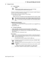
The owner of the system must be informed of audible bubbling noises and vapour pressure pulses during start-up in this case.
5.4.2 Additional settings for your solar system
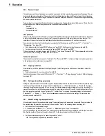
The following information on adjustments is applicable for operation without FlowSensor only:
In this case a FlowGuard (optional,
16 41 02
) should be installed at the flow connection of the hot water storage tank. Set
the water flow in the tank and solar panel circuits so the flow through every solar panel is 90 to 120 l/h. The flow volume is
controlled either by setting the speed stage on pumps P1/P2 or/and by setting the regulating valve with flow indicator at the
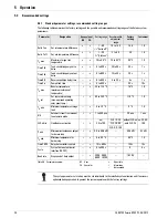
FlowGuard. Reference values for correct valve and pump stage settings are listed in table 5-6.
Always observe the system temperatures during normal system operation as indirect control of the flow volume. Under optimum
solar radiation (clear sky, clear air, sun vertical to solar panels) the temperature increase in the solar panels should be about 10
to 15 K. During operation with pump P1, for example at a return temperature of 50 °C, set the solar panel temperature at 60 to
65 °C. If a heat meter is installed in the building, the flow volume can be set by direct measurement during operation with a pump.
CAUTION!
If storage tank temperatures are over 60 °C a thermal mixing valve must always be installed at the hot water
connection of the storage tank for scalding protection.
CAUTION!
If a value >130 °C is set in the parameter cut-in protection temperature T
K
zul, this may result in vapour
pressure pulses that could damage the solar system.
To prevent pressure pulses, set the parameter cut-in protection temperature T
K
zul
ŭ
130 °C.
During operation of the solar system with FlowSensor, the flow in the solar system is continuously adjusted
for the requirements with the differential temperature-dependent control system of pump P1.


