background image

USER MANUAL


ENGLISH

rothaudio.co.uk  

|  5

Caution

Never remove the back covers of the audio system as this can expose 
you to very high voltages and other hazards. If the system does not 
operate properly, unplug the audio system and call your authorized 
dealer or service center. Adjust only those controls that are covered in 
the instructions, as improper changes or modifications not expressly 
approved by Roth AV could void the user’s warranty.

Warning

• 

To reduce the risk of fire or electric shock, do not expose this apparatus to rain or moisture.

• 

The system should not be exposed to dripping or splashing and objects filled with liquids, such 
as vases, should not be placed on the system.

• 

This apparatus shall be connected to a mains socket outlet with a protective earthing connection.

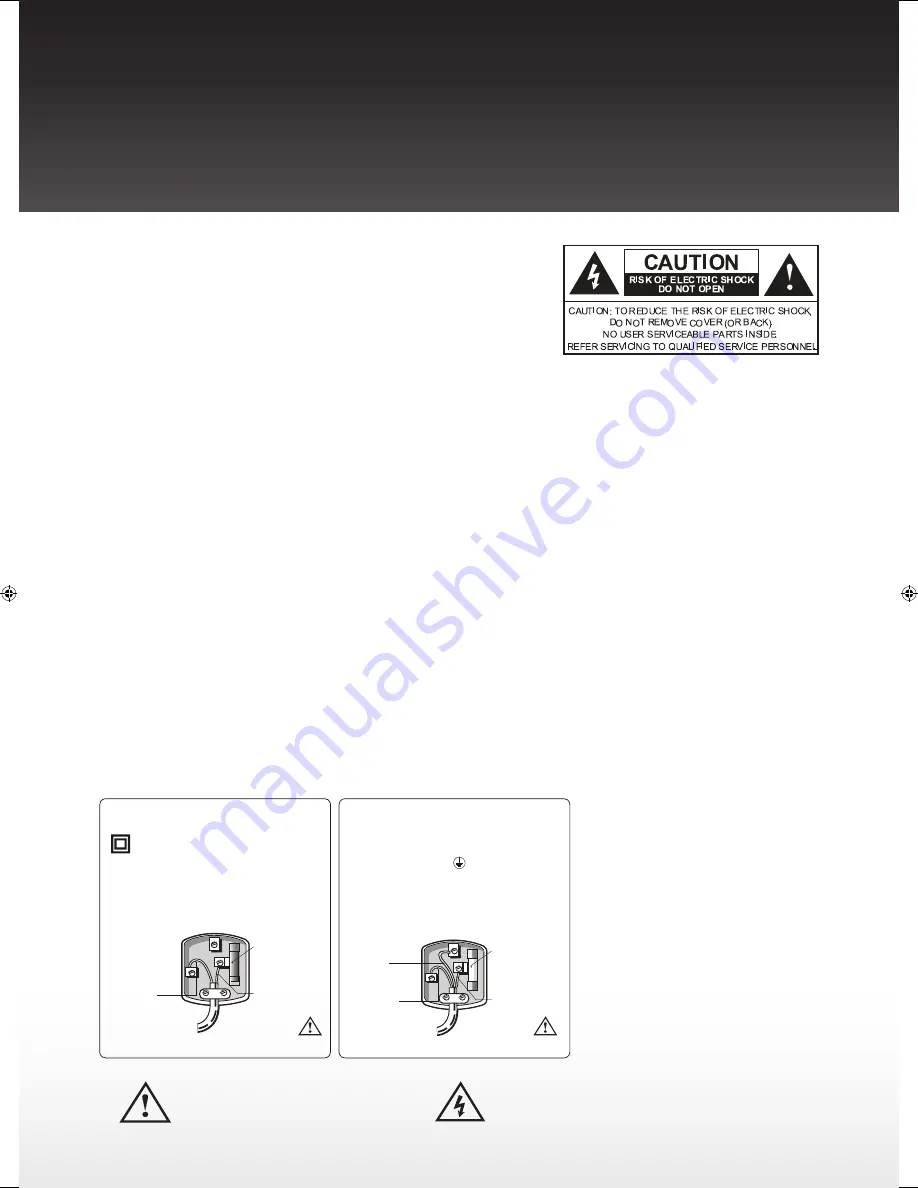
Electrical Information

This system is fitted with a BS1363/A 13 amp plug. If it is not suitable for your 
supply sockets it must be removed and replaced with an appropriate plug. 
If the plug becomes damaged and/or needs to be replaced please follow the 
wiring instructions below. The plug removed must be disposed of immediately. 
It must not be plugged into a supply socket as this will be an electrical hazard. If 
the fuse needs to be replaced it must be of the same rating and ASTA approved 
to BS1362. If the plug is changed, a fuse of the appropriate rating must be fitted 
in the plug, adapter or at the distribution board. If the fuse in a moulded plug is 
replaced, the fuse cover must be refitted before the appliance can be used.

Wiring Instructions

The supply cable will be either 2-core or 3-core. Follow the appropriate wiring 
instructions given below. In both cases ensure that the outer sheath of the 
cable is firmly held by the cable clamp.

Precautions

• 

Do not place the system on uneven 
surfaces or near the edge of the 
cabinet, it has high potential 
to tumble over, it may damage 
the product, it may also cause 
personal injury.

• 

Do not climb on the system, it may 
drop or may damage the system, it 
may also cause personal injury.

• 

Unplug immediately if any foreign 
materials falls into the system, or if 
the system fell down.

• 

Unplug immediately if there is a 
malfunction on the system like no 
sound or if there is smoke and bad 
odor coming from the system.

• 

Do not open the system’s cabinet.

• 

Avoid direct sunlight, dusty, high 
humidity and smoky locations.

• 

Remember to unplug the power 
cord from the AC outlet before 
cleaning. Do not use liquid 
cleaners or aerosol cleaners to 
clean the system.

• 

Do not place the system near 
water, such as a bathtub, shower 
rooms, kitchen sink, laundry tub 
or swimming pool. Avoid placing 
liquid containers on top of the 
system.

• 

Do not place the system in 
confined spaces or inside a box 
when the system is operating.

• 

Make sure to unplug the system 
when not in use for a long period 
of time (days).

Notice for Remote Control

• 

Avoid dropping the unit.

• 

Avoid liquids on it.

• 

Avoid aerosol cleaners.

The lightning flash with arrowhead symbol, within an equilateral triangle, 
is intended to alert the user to the presence of uninsulated “dangerous 
voltage” within the product’s enclosure that may be of a sufficient 
magnitude to constitute a risk of electric shock to a person.

The exclamation point within an equilateral triangle, is 
intended to alert the user to the presence of important 
operating and maintenance (servicing) instructions in 
the literature accompanying the appliance.

2- Core plug

WARNING!


Do not connect either wire to the earth terminal.


This symbol indicates that this 2-core 
appliance is Class II and does not require an 

earth connection. 
The wire coloured blue must be connected to the 
terminal marked with the letter N or coloured black.  
The wire coloured brown must be connected to the 
terminal marked with the letter L or coloured red

Blue 

(Neutral)

Fuse

Brown 

(Live)

WARNING!


This appliance must be earthed.

3- Core plug

The wire coloured green and yellow must be 
connected to the  terminal marked with the letter 
E, or by the earth symbol 

 or coloured green or 

green and yellow.
The wire coloured blue must be connected to the 
terminal marked with the letter N or coloured black.
The wire coloured brown must be connected to the 
terminal marked with the letter L or coloured red.

Blue 

(Neutral)

Fuse

Brown 

(Live)

Green & 

Yellow 

(Earth)

Roth SoundBar Manual EH.indd   5

7/3/11   11:19:59

Summary of Contents for BAR 1

Page 1: ...ROTH BAR 1 High power audio for your living room TM ...

Page 2: ...ccessories 6 Getting started 7 Wall mounting 8 Setup instructions hookup guide 9 Controls and functions 10 11 Wireless link 12 Hookup diagram 13 Specifications 14 Troubleshooting 15 Thank you For taking the Roth AV BAR1 home We ve designed the BAR1 to look beautiful and utilising the very best available amplification and driver technology sound great too We really hope you like the results Turn It...

Page 3: ...h larger audio system Another advantage to the Class HD amplifier is that there is no need for bulky external power adapters The BAR1 and Wireless Subwoofer have independent AC power cords so that the Subwoofer can be placed anywhere in the listening room State of the Art Processing Fractal Expansion FX Experience a convincing surround sound presentation from the10 speaker BAR1 and Subwoofer Fract...

Page 4: ...n a cart is used use caution when moving the cart apparatus combination to avoid injury from tip over 13 Unplug this apparatus during lightning storms or when unused for long periods of time 14 Refer all servicing to qualified service personnel Servicing is required when the apparatus has been damaged in any way such as power supply cord or plug is damaged liquid has been spilled or objects have f...

Page 5: ...lug immediately if any foreign materials falls into the system or if the system fell down Unplug immediately if there is a malfunction on the system like no sound or if there is smoke and bad odor coming from the system Do not open the system s cabinet Avoid direct sunlight dusty high humidity and smoky locations Remember to unplug the power cord from the AC outlet before cleaning Do not use liqui...

Page 6: ...ery Installation Caution Do not insert battery with and polarities reversed as this may cause the battery to swell or rupture resulting in leakage Remove the battery if the remote control is not going to be used for an extended period of time Do not put the battery in the general household trash Dispose of the battery according to applicable laws BAR1 Wireless Subwoofer BAR1 Table Stands BAR1 Remo...

Page 7: ...page 8 of this Owners Guide You can place the Subwoofer on the floor Step 1 Insert the top tab of the stand into the hole provided for the stand in the back of the BAR1 Step 2 Make sure that the top tab is fully inserted into the hole Step 3 Swing down the stand all the way until the stand hits the Soundbar so that the base of the stand will be underneath of the bottom of the BAR1 Then push up the...

Page 8: ...e distance down from the TV on each side 4 Make another mark 25 32 20 mm directly below the 1st mark on each side 5 Drill a hole in the wall at each of the four pencil marks 6 Hammer the 4 wall mount anchors into the holes the anchors should be flush with the wall 7 Now using a Philips screwdriver screw the wall brackets in place with the screws going into the anchors 8 Tilting the bottom of the B...

Page 9: ... control buttons on the front panel of the BAR1 will always function no matter what the audio input source is Note Some TV s do not have a headphone output but do have Audio outputs with RCA jacks You can connect them to Input 1 by using the RCA cable This will also work fine except that the BAR1 volume must now be adjusted using the BAR1 remote 4 The remaining inputs Input 2 can be attached to Bl...

Page 10: ... FX STEREO ST Indicator The FX indicator lights up when FX Surround is selected The ST indicator lights up when Stereo Mode is selected This indicator will turn off after about 3 seconds from selecting the surround setting 4 MUTE ON Indicator This indicator lights up when mute is on This indicator will turn off after about 3 seconds from turning mute on 5 MAIN VOLUME SUBWOOFER VOLUME Level Indicat...

Page 11: ...he BAR1 and the Subwoofer Press and hold this button at least 3 seconds until the PAIR indicator on the front panel starts flashing Then press the PAIRING button on the rear panel of the Subwoofer The two units should link back up 15 INPUT 3 Connection type 3 5 mm mini stereo If your TV has a headphone output this is a primary input to use by using the supplied 3 5 mm mini stereo cable 16 INPUT 2 ...

Page 12: ...quipment for the BAR1 and the Subwoofer to lose their wireless link In that case the Subwoofer will mute and the audio will sound weak no bass To correct this press and hold the PAIRING button on the back of the BAR1 at least 3 seconds until the PAIR indicator on the front panel starts flashing Then go to the back of the Subwoofer and press its PAIRING button The two units should link back up and ...

Page 13: ...u ray DVD or CD players It can also be used to connect devices such as MP3 players or Home Video Game systems BAR1 To Input 2 RCA jack of BAR1 RCA Cable To Audio Output Other Device Blu ray Players DVD Players CD Players MP3 Players Home Video Game Systems BAR1 Rear Connectors BAR1 RCA Cable Supplied To Audio Output of Set Top Box or TV To Input 1 RCA jack of BAR1 Note Some TV s do not have a head...

Page 14: ... and play Connection Only AC Power plug in is required Wireless range up to 100 feet Clear line of sight Inputs 2 RCA Stereo Connectors TV DVD DVRs or Set Top Box 1 3 5 mm Stereo Mini Jack TV MP3 Players Power Input BAR1 AC 230V 50Hz Subwoofer AC 230V 50Hz Convenience Features LED Display with Auto Dimming Volume Mute Surround Mode Recessed Input Terminals for Flush Wall Mount Capability Table Sta...

Page 15: ...es are securely connected at the terminals of the BAR1 and the external devices 4 2 Test on an alternate device or replace the audio cable 4 3 Test the device and cable on an alternate input on the BAR1 5 The remote control does not work 5 1 Aim the remote control directly at the sensor on the front of the BAR1 5 2 Reduce the distance between the remote control and the BAR1 5 3 Make sure that the ...

Page 16: ...haudio co uk Service www rothaudio co uk In accordance with our policy of continuous development we reserve the right to change specifications without notice Photographs are for illustration only and actual product may vary E OE Find us on Facebook Just search for Roth AV ...

Reviews: