ENGLISH
21
Insert the plastic pipe or fitting in the clamping device (use dolly with longer pipe < 2,5m sec-
tions) and tighten brass nut on the upper clamps. Adjust brass nuts (tighten or loosen) to
compensate for any ovalness.
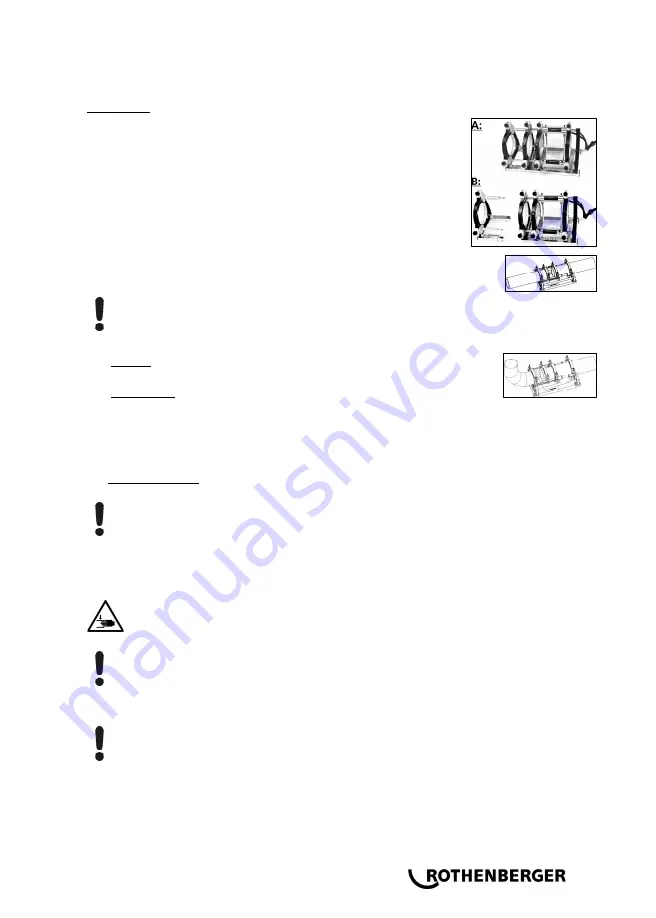
For P200B:
The machine is operated with 4 basic clamping jaws in the case
of pipes/ pipe connections (welding position A).
The 4th basic clamping jaw can be removed in the case of
narrow pipes/ fitting connections (welding position B). To do
this, initially remove the screws (3) and then slightly loosen the
screws (5). The 4th jaw can now be pulled out together with the
sub-construction. Finally, unscrew the spacers (4) and replace
them by the screws (3).
For pipe-to-pipe connections, the two spacers must be engaged in
both left clamping elements (standard configuration at delivery).
Attention: Under no circumstances should the spacers be installed diagonally offset!
The pipes are each held by two clamping elements.
P160B: For pipe-to-fitting connections, the two spacers must be en-
gaged in both middle clamping elements.
P250-355B: For pipe-to-fitting connections, the two spacers must be
engaged in both middle clamping elements, and the heating element
take-off device is suspended into the left clamping elements. When
some fittings are being processed in certain positions, such as horizon-
tal bends or welding necks, it is necessary to remove the heating ele-
ment take-off device.
P500-630B Plus: For pipe-to-fitting connections, the spacers must be swivelled to the other
side and engaged in the middle clamping elements
Attention: Under no circumstances should the spacers be installed diagonally offset!
The pipe is inserted into three clamping elements, and the fitting is held by one clamping el-
ement. Thus, the movable clamping element can be shifted on the rod as space require-
ments demand during clamping.
Verify secure fit by moving the workpieces together.
Stay a safe distance away from the machine. Do not stand or reach into the machine.
Keep other people away from the work area!
Check to ensure that the heating plate has reached the setpoint operating temperature.
CAUTION! To guarantee uniform heat distribution over the entire heating element, the
heating element must not be used until at least 10 minutes after it reaches the target
temperature. Check and verify the temperature with a temperature meter and readjust if
necessary!
Position the electrical trimmer between the two workpieces.
P500-630B Plus: Verify the direction of rotation! The machines were polarized to turn
clockwise before leaving our factory!
Switch on trimmer unit. The planing discs should turn in the cutting direction; if not, use suit-
able tools to change over the phase inverter in the mains plug.
Summary of Contents for 055180H
Page 159: ...NOTES ...


